Do you have a question about the Hitachi RPF Series and is the answer not in the manual?
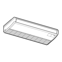
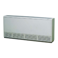
The RPF(I) unit, specifically models RPF(I)-(1.0-2.5)FSN2E, is an indoor air conditioning unit designed for standard air conditioning in human-occupied spaces. It is not intended for use with an electrical heater and should not be installed in environments where flammable gases, oil vapors, or corrosive atmospheres (acidic, alkaline, or high sulfurous gas concentration) are present, as these conditions can lead to fire, deformation, corrosion, or system failure. Installation in areas with silicon gas is also prohibited, as silicon deposits on the heat exchanger can repel water, causing condensate to splash into the electrical box and potentially leading to water leaks or electrical faults. The unit should also not be installed where expelled air directly affects animals or plants.
The model classification for the indoor unit is RPF(I), followed by a fixed position-separating hyphen. The capacity is indicated in HP, ranging from 1.0 to 2.5. "FS" denotes a SYSTEM FREE unit, "N" indicates R410A refrigerant, "2" signifies the series, and "E" means "Made in Europe."
Piping connections vary by model. For RPF(I)-1.0/1.5 units, the gas piping is Ø12.70 (5/8 inches), liquid piping is Ø6.35 (1/4 inches), and drain piping is Ø18.5 OD. For RPF(I)-2.0 units, the gas piping is Ø15.88 (5/8 inches), liquid piping is Ø6.35 (1/4 inches), and drain piping is Ø18.5 OD. For RPF(I)-2.5 units, the gas piping is Ø15.88 (5/8 inches), liquid piping is Ø9.53 (3/8 inches), and drain piping is Ø18.5 OD.
The unit is designed for optimal air distribution within a room to achieve uniform air temperature. It is recommended to install indoor units 2.3 to 3 meters from the floor level. If installed higher than 3 meters, a fan is recommended to ensure uniform air distribution. Obstacles that may hinder air intake or discharge flow should be avoided.
For installations in hospitals or other locations with electromagnetic wave-emitting medical equipment, special precautions are necessary. The electrical box, remote control cable, and remote control switch should not be directly exposed to electromagnetic waves. It is advised to install the remote control switch in a steel box and route its cable through a steel conduit, with both the box and conduit properly grounded. The unit, outdoor unit, remote control, and cables should be installed at least 3 meters away from strong electromagnetic radiation sources.
The unit should only be used by adults and capable individuals who have received technical information or instructions for proper and safe handling. Children should be supervised to prevent them from playing with the appliance. Regular ventilation of the room (every 3-4 hours) is recommended.
The RPF(I) unit includes several components for easy maintenance. Key parts include the fan casing, fan, fan motor, heat exchanger, expansion valve, distributor, air filter, refrigerant gas pipe connection, refrigerant liquid pipe connection, electrical control box, air inlet, air outlet, and drain pipe connection.
A service access door or panel should be provided around the indoor unit for operation and maintenance. For RPF units, the front and side covers must be removed to access internal components. For RPFI units, a service access cover fixed with screws is recommended to prevent direct contact with the fan runner.
The unit's flat level can be adjusted using installation bolts, ensuring the drain pipe side is lower than the opposite side for smooth drainage. The base plate and back plate are fixed with field-supplied bolts and screws. The electrical wiring box should be removed when attaching the adjusting bolts.
Twisted shielded pair cables or shielded pair cables should be used for transmission wires between indoor and outdoor units. The shielded part must be connected to the earth screw in the electrical box of the indoor unit. The unit must be connected to a circuit breaker of the specified capacity.
DIP switches (DSW3, DSW4, DSW5, DSW7, RSW1, RSW2) are used for various settings, including capacity code, unit model code, refrigerant cycle number, fuse recovery, and remote control selection. Before adjusting DIP switches, the power source must be turned off to ensure settings are valid.
Drain piping should not have an upward slope or rise, as this can cause drain water to flow back into the unit and lead to leaks when the unit is stopped. It should not be connected to sanitary or sewage piping. If a common drain pipe is used for multiple indoor units, each indoor unit's connection point must be higher than the common piping, and the common drain pipe size must be adequate for the number and size of units.
Drain piping requires insulation if installed in a location where condensation may form on the outside of the pipe, potentially causing damage. The insulation must ensure vapor sealing to prevent condensation. A drain trap should be installed next to the indoor unit, designed for good practice, and tested with water for correct flow. The drain pipe and refrigerant pipe should not be tied or clamped together. Drainage should be installed in accordance with national and local codes.
After drain piping and electrical wiring, approximately 1.8 liters of water should be poured into the drain pan to check for smooth flow and absence of leaks. If no water appears at the end of the drain piping, another 1.8 liters should be poured. When connecting the drain pipe on the left side, care must be taken with insulation thickness to ensure the pipe can be installed within the unit. A polyvinyl chloride pipe with an 18.5 mm outer diameter is used for drain piping, and it should be insulated after connecting the drain hose.
| Brand | Hitachi |
|---|---|
| Model | RPF Series |
| Category | Air Conditioner |
| Language | English |