7
Fig. 10
䡬 When bending multiple rebars at one time, some may
come off the bending roller and guide, etc., and
therefore exercise caution and set them horizontally.
䡬 If you bend the rebar with a large angle while placing
your hand onto it, there is a fear of getting your hand
caught in by the fold-back reaction of the rebar. Never
place your hand onto the position where the rebar
may fold back.
䡬 Do not bend more than 50 rebars in one session as
this will overload the motor, and may cause it to burn
out.
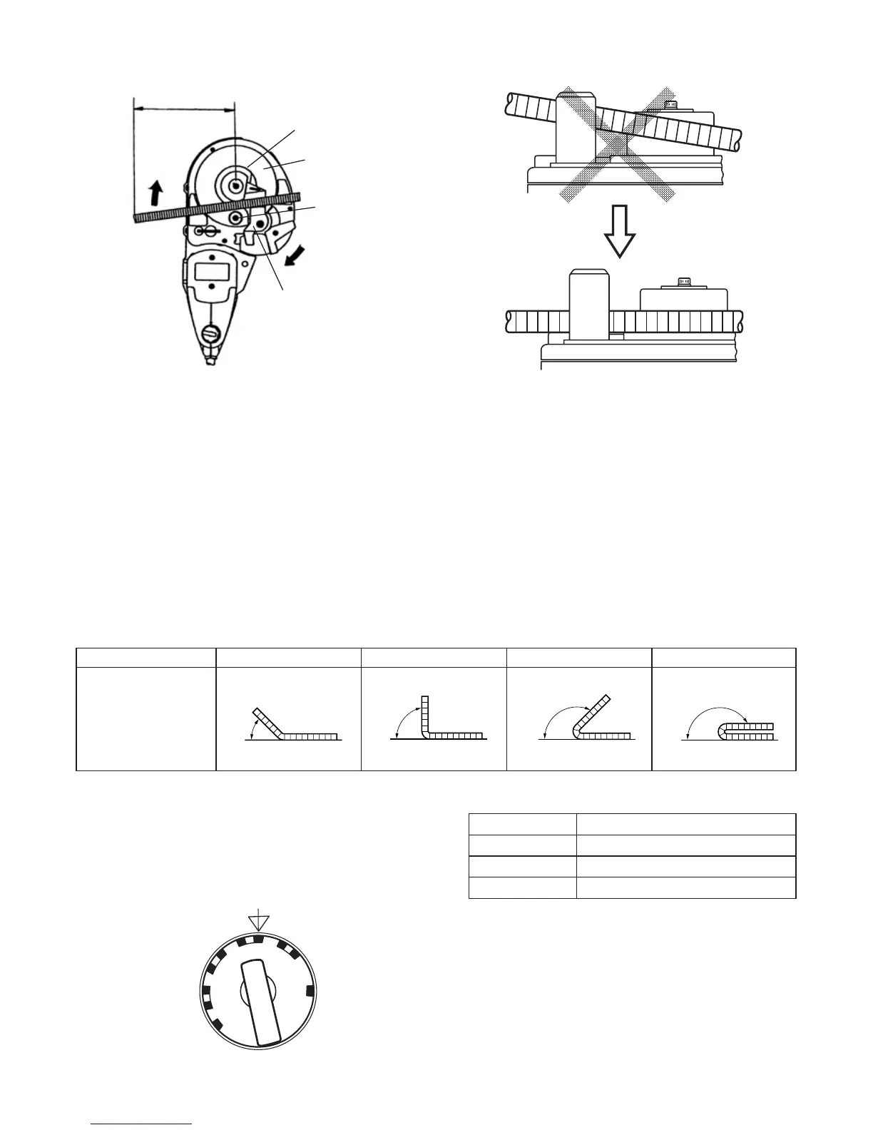
1. Setting bending angles by setting dial
The bar can be bent according to the angles indicated
on the setting dial, as shown in Fig. 11.
In bending the rebar of 10 mm, 12 mm, and 16 mm
diameters, a difference takes place in the bending angle
even in the same dial position depending upon the
difference of rebar’s thickness. Slightly change a
position of the setting dial depending upon the rebar’s
diameter even with the same bending angle as illustrated
in the top diagram on the left column. (Fig. 12)
Fig. 12
Size of rebar Colors of indicated marks
ø10 mm White
ø12 mm Red
ø16 mm Yellow
NOTE:
Even at the same dial setting position, the bending
angle can sometimes differ if the diameter or hardness
of the rebar is different. Use the angle marks merely
as a rough guideline.
2. Ordinary bending
(1) Set the unit in the position with the turntable up as
shown in Fig. 13.
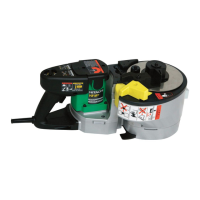
䡬 Place the rebar on the center plate and set it so that it
is horizontal with the turntable surface.
If the side that is to be bent is set inclined upward, the
rebar can come loose from the bending roller while
bending causing it to fly off. (Fig. 10)
Fig. 9
Center plate
Stopper
200 mm
Bending roller
Turn table
Fig. 11
Condition of rebar
Dial indication 45° 90° 135° 180°
180°135°90°45°
0˚
RETURN
CUT
45˚
90˚
135˚
180˚
 Loading...