8
Fig. 13
(2) Make sure that the cover is closed.
(3) Set the setting dial at the desired angle.
(4) Place the rebar on the stopper of the center plate and
set it correctly as shown in Fig. 9.
(5) Pull the switch trigger and bent the rebar.
(6) Continue pulling the switch trigger untill the motor
makes reverse rotation and the bending roller starts
to return. (Once the bending roller starts to return, it
will automatically return all the way to the home
position even if the switch trigger is released.)
3. Bending by eye measurement
By pulling the switching trigger little by little, you can
bend the rebar to your desired angle by eye
measurement in addition to the dial setting.
(1) Set the setting dial to a larger angle than you desire.
(2) Pull the switch trigger lightly and bend the rebar
slowly.
(3) When the rebar is bent to the desired angle, stop
pulling the switch. If the bar is still small of the desired
angle, pull the switch again.
(4) Remove the rebar after bending has been finished.
Then, pull the switch once more and return the
bending roller to the home position. (Continue pulling
the switch until the bending roller begins reverse
rotation.)
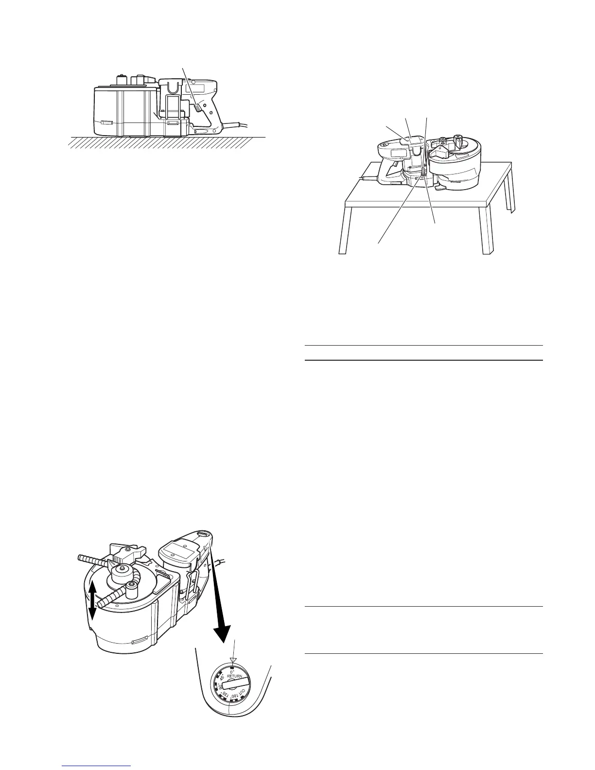
4. Removing rebar during bending operation
When bending out at a low speed in “bending by eye
measurement”, the rebar can sometimes get caught
in the bending roller due to its own flexure.
If this occurs, you can return the bending roller to the
home position by pulling the switch again after setting
the setting dial to the “return” position. This is the
same method used to remove the rebar when it gets
caught during cutting operation. (Fig. 14)
Fig. 14
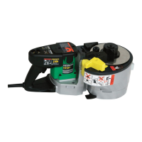
5. Using hole to fix unit in place
A hole is provided at the center of the unit to fix and
stabilize it. This hole comes in quite handy when used
in the following manner. (Fig. 15)
Fig. 15
䡬 For bending operation when the unit is fixed to a work
bench.
This hole will prove very convenient when the unit is
bolted to a suitable work bench. (Bolt size M10, less
than W3/8.)
MAINTENANCE AND INSPECTION
WARNING!
To prevent accidents, always be sure to turn the switch
OFF and unplug the power cord from the receptacle.
1. Inspecting the mounting screws
Regularly inspect all mounting screws and ensure that
they are properly tightened. Should any of the screws
be loose, retighten them immediately. Failure to do
so could result in serious hazard.
2. Maintenance of the motor
The motor unit winding is the very “heart” of the
power tool. Exercise due care to ensure the winding
does not become damaged and/or wet with oil or
water.
3. Inspecting the carbon brushes
For your continued safety and electrical shock
protection, carbon brush inspection and replacement
on this tool should ONLY be performed by a Hitachi
Authorized Service Center.
4. Replacing supply cord
If the supply cord of Tool is damaged, the Tool must
be returned to Hitachi Authorized Service Center for
the cord to be replaced.
NOTE:
Due to HITACHI’s continuing program of research and
development, the specifications herein are subject to
change without prior notice.
Switch trigger
Bolt
Tail cover
Set screws
Nut
Hole to fix unit
 Loading...