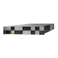
SFF rear panel
Number Item Description
1 PATH (IN) connector Connects to a controller or
drive tray.
2 PATH (OUT) connector Connects to a drive tray.
3 ENC N/A
4 PATH (IN) LED Blue: IN side port is linked
up.
5 PATH (OUT) LED Blue: OUT side port is linked
up.
6 Console These ports are reserved.
7 POWER LED Green: ENC is in the power-
on state.
8 LOCATE LED Amber:
■
Indicates the location of
the chassis.
■
Can be turned on or
turned off by the
maintenance utility.
9 ALARM LED Red: ENC can be replaced.
10 Power supply unit N/A
11 Receptacle Connects to the power cable
provided with the storage
system.
SFF rear panel
Chapter 2: Hardware overview
Hitachi Virtual Storage Platform E590 and E790 Hardware Reference Guide 30