


B
Bryan SmithAug 31, 2025
What to do if Hitachi Air Conditioner has Receiver Communication failure?
- RRobert McintyreAug 31, 2025
If your Hitachi Air Conditioner is not receiving a signal, check the Opentherm/Hlink connection.
What to do if Hitachi Air Conditioner has Receiver Communication failure?
If your Hitachi Air Conditioner is not receiving a signal, check the Opentherm/Hlink connection.
What to do if Hitachi Air Conditioner shows abnormal transmission between outdoor and indoor units?
If your Hitachi Air Conditioner shows 'Abnormal transmission between outdoor and indoor units', check the wiring, terminals, and PCB for faults. This issue can be caused by incorrect wiring, loose terminals, PCB failure, a tripped fuse, or the power supply being OFF.
Why does my Hitachi Air Conditioner activate safety device from excessively high discharge pressure?
If your Hitachi Air Conditioner activates the safety device due to excessively high discharge pressure, inspect the heat exchanger and refrigerant conditions. This activation can be caused by overload (obstruction of HEX, short circuit), a mixture of inert gas, or excessive refrigerant.
What causes Hitachi Air Conditioner to activate safety device from excessively low suction pressure?
If your Hitachi Air Conditioner activates the safety device from excessively low suction pressure, inspect refrigerant levels and piping for blockages. This issue is often due to a shortage or leakage of refrigerant, piping clogging, a closed expansion valve, or a locked fan motor.
How to troubleshoot Hitachi Air Conditioner hydraulic alarm flow and water pump malfunction?
If your Hitachi Air Conditioner displays a hydraulic alarm related to flow and water pump malfunction, check the water pump for proper operation and repair or replace it if defective. This alarm indicates that water flow is not detected in the hydraulic cycle or the pump is defective.
What to do if Hitachi Air Conditioner shows Thermostat Heater Alarm?
If your Hitachi Air Conditioner is showing a high temperature in the electric heater, check the electric heater for proper operation.
How to fix Hitachi Air Conditioner activation of overcurrent protection?
If your Hitachi Air Conditioner activates overcurrent protection, inspect the inverter PCB and compressor operation. This can be caused by overload, overcurrent, failure of the Inverter PCB, a clogged heat exchanger, a locked compressor, or EVI/EVO failure.
How do I fix a 'Unit Capacity setting Error' on my Hitachi Air Conditioner?
If your Hitachi Air Conditioner displays a 'Unit Capacity setting Error', ensure correct capacity settings for both indoor and outdoor units. This error indicates a mismatch between the indoor and outdoor unit capacities.
How to correct Hitachi Air Conditioner incorrect indoor unit number setting?
If your Hitachi Air Conditioner displays 'Incorrect indoor unit number setting', correct the indoor unit number settings. This issue can be caused by duplication of indoor unit numbers or the number of indoor units exceeding specifications.
How to fix Incorrect PCB Setting in Hitachi Air Conditioner?
If your Hitachi Air Conditioner shows 'Incorrect PCB Setting', correct the DSW settings. This issue is caused by a wrong DSW setting in the case of Co041.
Details on general notes, introduction, overview of YUTAKI system, and summary of operations.
Explanation of danger, caution, and note symbols used for safety and important information.
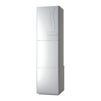
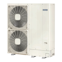
Classification of units into split and monobloc systems, detailing YUTAKI models.
DANGER and CAUTION statements regarding electrical connection, handling, and operation.
Read manual carefully, verify information, note continuous improvement policy, and intended use.
Nominal capacity-performance tables, including considerations and specific data for YUTAKI S.
Details on ERP data for space heaters, including average climate data for YUTAKI S.
Includes considerations, outdoor unit specifications for split systems, and refrigerant details.
Information on air heat exchangers, fans, motors, and compressors for split systems.
Power supply, applicable voltage, and current ratings for outdoor and indoor units.
Details on nominal power supply, operating voltage, and voltage imbalance for 3N~ 400V 50Hz.
Working ranges for space heating, DHW, swimming pool heating, and space cooling.
Hydraulic data including minimum and maximum water flow rates and installation water volumes.
Diagrams and part lists for YUTAKI S, S COMBI, and S80 split systems.
Diagram and part list for YUTAKI M monobloc system.
Information on refrigerant piping length, size, and precautions for leaks.
Water piping length guidelines and water quality recommendations for optimal performance.
Recommendations for water quality and DHW circuit to prevent scale and corrosion.
Checks for power supply installation, voltage, impedance, and compliance with EMC directives.
Guidelines for wiring size, power supply cables, transmitting cables, and actuator cables.
Location and function of DIP switches and rotary switches for outdoor unit test run modes.
Details on main power supply and indoor/outdoor communication wiring for TB1 and TB2.
Identification and function of buttons on the PC-ARFHE unit controller.
Explanation of common icons, comprehensive view icons, and room thermostat view icons.
Detailed breakdown of the controller's menu structure across multiple levels.
Description of the comprehensive view and room thermostat view on the controller display.
Step-by-step guide for initial system configuration using the Configuration Assistant or Advanced Configuration.
Displays general information, circuit status, DHW, swimming pool, heat pump, and energy data.
Configuration options for General, Timers, Water settings, Space Heating, Cooling, DHW, and Pool.
Settings for Controller Options, Room Names, Date/Time, Screen Settings, and Language Selection.
Procedures for Air Purge, Unit Test Run, and Screed Drying.
Provides system information and contact details for the controller.
List of alarm codes for indoor units, detailing abnormalities and main factors.
List of alarm codes for outdoor units, detailing abnormalities and main causes.
General precautions and guidelines for inspection and maintenance tasks.
Detailed steps for maintaining the fan, heat exchanger, piping, cabinet, and electrical equipment.
Checks for cabinet, water piping, water flow, pressure, fixing points, electrical equipment, and control devices.
Details on general notes, introduction, overview of YUTAKI system, and summary of operations.
Explanation of danger, caution, and note symbols used for safety and important information.
Classification of units into split and monobloc systems, detailing YUTAKI models.
DANGER and CAUTION statements regarding electrical connection, handling, and operation.
Read manual carefully, verify information, note continuous improvement policy, and intended use.
Nominal capacity-performance tables, including considerations and specific data for YUTAKI S.
Details on ERP data for space heaters, including average climate data for YUTAKI S.
Includes considerations, outdoor unit specifications for split systems, and refrigerant details.
Information on air heat exchangers, fans, motors, and compressors for split systems.
Power supply, applicable voltage, and current ratings for outdoor and indoor units.
Details on nominal power supply, operating voltage, and voltage imbalance for 3N~ 400V 50Hz.
Working ranges for space heating, DHW, swimming pool heating, and space cooling.
Hydraulic data including minimum and maximum water flow rates and installation water volumes.
Diagrams and part lists for YUTAKI S, S COMBI, and S80 split systems.
Diagram and part list for YUTAKI M monobloc system.
Information on refrigerant piping length, size, and precautions for leaks.
Water piping length guidelines and water quality recommendations for optimal performance.
Recommendations for water quality and DHW circuit to prevent scale and corrosion.
Checks for power supply installation, voltage, impedance, and compliance with EMC directives.
Guidelines for wiring size, power supply cables, transmitting cables, and actuator cables.
Location and function of DIP switches and rotary switches for outdoor unit test run modes.
Details on main power supply and indoor/outdoor communication wiring for TB1 and TB2.
Identification and function of buttons on the PC-ARFHE unit controller.
Explanation of common icons, comprehensive view icons, and room thermostat view icons.
Detailed breakdown of the controller's menu structure across multiple levels.
Description of the comprehensive view and room thermostat view on the controller display.
Step-by-step guide for initial system configuration using the Configuration Assistant or Advanced Configuration.
Displays general information, circuit status, DHW, swimming pool, heat pump, and energy data.
Configuration options for General, Timers, Water settings, Space Heating, Cooling, DHW, and Pool.
Settings for Controller Options, Room Names, Date/Time, Screen Settings, and Language Selection.
Procedures for Air Purge, Unit Test Run, and Screed Drying.
Provides system information and contact details for the controller.
List of alarm codes for indoor units, detailing abnormalities and main factors.
List of alarm codes for outdoor units, detailing abnormalities and main causes.
General precautions and guidelines for inspection and maintenance tasks.
Detailed steps for maintaining the fan, heat exchanger, piping, cabinet, and electrical equipment.
Checks for cabinet, water piping, water flow, pressure, fixing points, electrical equipment, and control devices.
| Type | Air-to-Water Heat Pump |
|---|---|
| Energy Efficiency Class (Cooling) | A++ |
| Refrigerant | R32 |
| Operating Temperature Range (Heating) | -20°C to 35°C |
| Energy Efficiency Class (Heating) | A+++ |
| Integrated DHW Tank | 190 liters |
| Dimensions (Indoor Unit) | Varies by model |
| Dimensions (Outdoor Unit) | Varies by model |
| Weight (Indoor Unit) | Varies by model |
| Weight (Outdoor Unit) | Varies by model |
| Operating Temperature Range (Cooling) | +10°C to +46°C |