.
Doc. no.: Rev0.0
Issue date: 2020.07.29
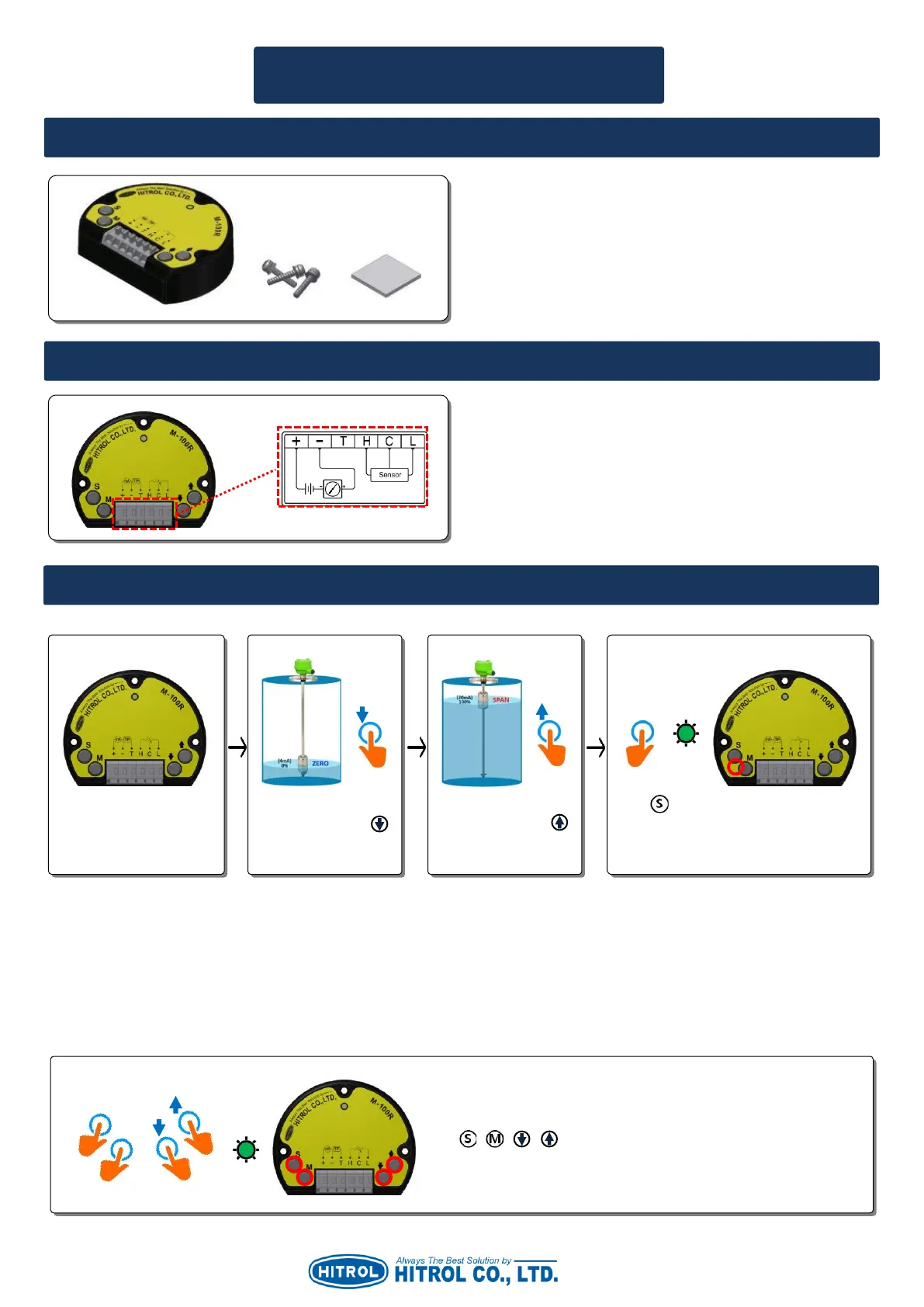
1. Basic Components (It is applied when M-100R is supplied individually.)
User Manual for M-100R
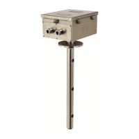
■ ZERO/SPAN Setting
▷ The order of Step. 2 and Step. 3 can be changed.
▷ Zero(0%) can be set individually as Step. 1 Step. 2 Step. 4 in order.
▷ Span(100%) can be set individually as Step. 1 Step. 3 Step. 4 in order.
※ Caution: If wrong setting, Yellow LED will be flickering and 3.6mA current will be out.
■ Auto Setting (Applied to HT-100R Series Only.)
In case the M-100R to be replaced without separation of the sensor from the tank, set it as below.
▷ It is recommended to set Zero/Span during the maintenance period of the tank.
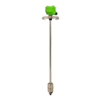
▷ +, - : DC +24V (DC 2-wire 4~20mA Loop)
▷ T : Current Output Test Point
▷ H.C.L : Terminal for Sensor Wiring
1. M-100R
2. SEMS Bolt M3 x 14L 304SS
3. 3M VHB Strong Double Tape (2.54cm x 2.54cm)
When power is connected,
Green LED is ON.
Place a float at 0%
position and press
button on the M-
100R (R/I Converter).
Place a float at 100%
position and press
button on the M-100R
(R/I Converter).
Press button for about 1 second until
the Green LED is flickering. Then, Zero /
Span will be set simultaneously.
Press + + + buttons at once for about 1 second until Green
LED is flickering. Then, Zero/Span will be set automatically.