Do you have a question about the Hitron HM-90 Series and is the answer not in the manual?
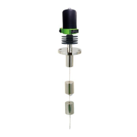
Key features and design characteristics of the HM-30, 90 Series level detector.
Technical specifications for the weather-proof model including temperature, pressure, and connections.
Technical specifications for the explosion-proof model including temperature, pressure, and connections.
Detailed dimensional drawings for weather-proof versions across various temperature ranges.
Detailed dimensional drawings for ex-proof versions across various temperature ranges.
Illustrations and dimensions for the Guide Pipe Version (HM-90A) installation.
Illustrations and dimensions for the Chamber Version (HM-90B) installation.
Explanation of how the switch operates based on displacer movement and core position.
Contact rating specifications for the switch based on different process temperature ranges.
Diagrams and instructions for Single Pole Double Throw (SPDT) switch wiring.
Diagrams and instructions for Double Pole Double Throw (DPDT) switch wiring.
Guidelines and conditions for the proper installation and adjustment of the level switch.
Specific maintenance recommendations for the chamber component of the level switch.
Maintenance advice for the switch housing, focusing on sealing and wiring integrity.
General precautions for safe and correct usage of the product.
Safety guidelines to follow when performing wiring connections.
Instructions on how to properly dispose of the product or its components.
Information about the product identification mark and its contents.
Details on product warranty, service policies, and how to request support.
Contact information for headquarters, factory, and laboratory for inquiries and service.
The HITROL HM-30, 90 Series is a displacer type level switch designed for detecting upper and lower liquid limits in vessels. It provides ON/OFF contact signals and is engineered for high temperature and pressure applications, offering excellent reliability. This device is commonly used as a water level detector in boilers of power plants and refining equipment in petrochemical plants.
The HM-30, 90 Series operates based on the buoyancy of a displacer and the tension of a spring. When the liquid level rises and the displacer becomes submerged, it experiences buoyancy, making it lighter. This causes the compressed spring to release, allowing a core to rise within an enclosing tube. A magnet connected to the switch then responds to the rising core, triggering the switch. The device can be installed on top of a tank or a connected chamber.