4
INITIAL SETUP / INSTALLATION
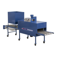
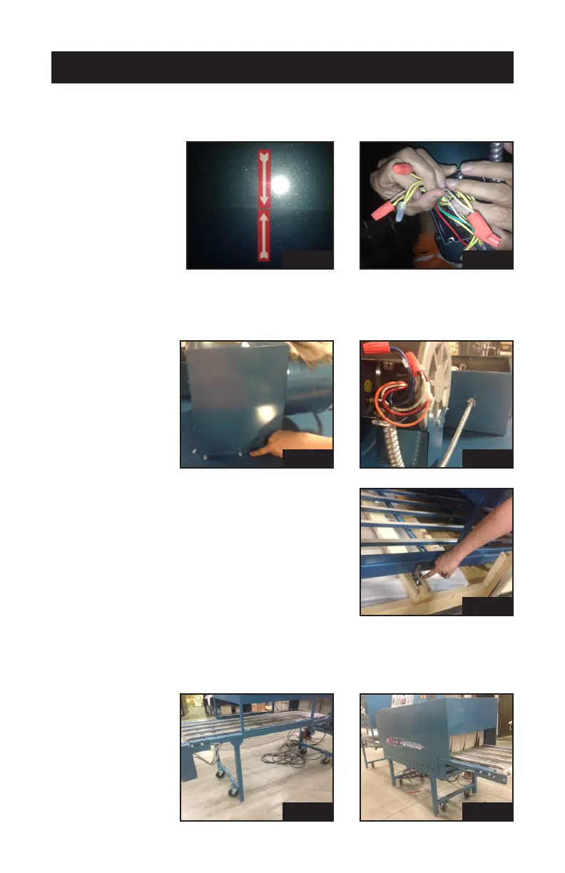
Red/white arrow decals should point toward each other when the con-
gurationiscorrect(pic5b).Similarlynumberedwiresconnecttogeth-
er with the orange wire nuts (also in pack)(pic 5c).
6. The exhaust fan assembly attaches to the top with ten #14 x ½” hex
head tap screws. (pic 6a). The wires to the assembly are not num-
bered and can be fastened either way with the orange wire nuts.
7. The cooler section has four 3/8” headed
lag screws to be removed before lifting
the unit off the crate base.
8. The 2414 model has only one set of legs (pic 8a) with angle iron tabs
on the exit side only. The entry side has arm extensions only (pic 8b).
Fasten the two sections together with the 3/8-16 x 1” bolts already in
the tabs.
pic 1
pic 1
pic 1
pic 1
pic 1
pic 1
pic 1