5
INITIAL SETUP / INSTALLATION
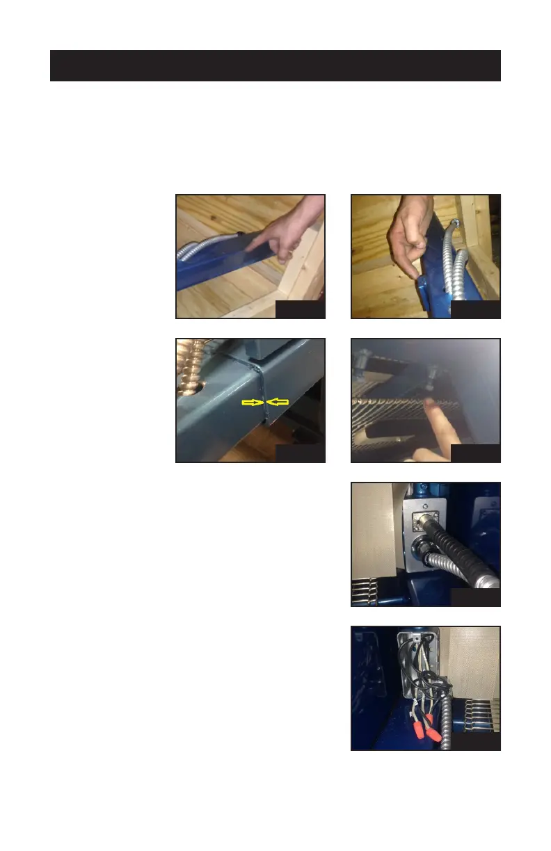
9. The 3626 model has two sets of legs on the exit side, both self-sup-
porting once installed. The 4827 model has 3 sets of self-supporting
legs.
The telescope tubing (pic 9a) slides into the oven frame until it hits the
metal stops (pic 9b and c). Next, tighten the four 9/16” headed bolts to
secure them together (pic 9d).
10. Insert the gear box quick-connectors into
the handy box, located under the oven’s
fume hood at the exit side. One connects
with a twist lock, the other with a snap
lock (pic 10).
11. The cooler unit’s wires are numbered to
match up with the wires in the electrical
handy box. Remove handy box cover,
run the wires and ex conduit into the
90˚ Romex connector and tighten the
screws. Tie the similarly numbered wires
together with orange wire nuts (pic 11).
Then replace the handy box cover.
pic 1
pic 1
pic 1
pic 1
pic 1
pic 1