EasyManua.ls Logo

Hix TT-180D - User Manual

Hix TT-180D
12 pages
Print Icon
To Next Page IconTo Next Page
Loading...
12
WARRANTY
1201 E. 27th Terrace • Pittsburg, KS 66762 • U.S.A.
Web site: www.hixcorp.com • Phone: (800) 835-0606 • Fax: 620-231-1598
E-Mail: customerservice@hixcorp.com • E-Mail: sales@hixcorp.com
©2015 HIX Corp.
Design and Manufacturers of Graphic Imaging, Commercial Food, Industrial and Custom Drying Equipment
(Effective October 30, 2015)
HIX will automatically register the equipment on the date it was shipped to you or your distributor. If the
equipment was not purchased directly from HIX, but through a distributor (either domestic or foreign), please
keep a copy of their sales invoice showing the serial number and date it was sold/shipped to you with this war-
ranty. In this case, we will use the distributors invoice date as the beginning warranty date. STAPLE A COPY
OF YOUR RECEIPT TO THIS WARRANTY and keep in a safe place to provide veri cation of your warranty
should a problem occur. Thank you.
Please ll in the following information and attach a copy of your receipt for your records.
Date Purchased: From:
Model #: Serial #:
This warranty applies to equipment manufactured by the HIX Corporation (HIX), Pittsburg, Kansas, U.S.A.
HIX warrants to the original purchaser, its Ovens and Dryers, Heat Transfer Presses, Mug Presses, Mug Glazer,
Retensionable Screen Frames, Textile Printers, Spot Heaters, and Exposure Units against defects in workman-
ship and material, except for wear and tear for a period of “One Year” from the date of purchase. HIX warrants
its Accessories, Reten Splines/Hardware/Tool Kit, and Shuttle for a period of 90 days from the date of purchase.
Thermatrol and doughXpress products are covered under separate warranty.
In the event of a defect, HIX, at its option, will repair, replace or substitute the defective item at no cost during
this period subject to the limitations of insurance and shipping costs stated below.
In the case of heat transfer presses (except the Hobby Lite), HIX warrants the heat casting for the “Life” of the
machine for the original purchaser. If a part becomes obsolete at the time for repair, and/or cannot be reason-
ably substituted for, HIX will credit, at half the then current list price or last recorded price, only that part toward
a new machine or any product HIX offers. This credit offer shall be the sole responsibility of the HIX Corporation
in the event of an obsolete part.
This warranty does not cover belts, rail tape, pads, mug wraps, canvas, rubber blankets, bulbs, glass, rod
ends, turn buckles on printers or damages due to accident, misuse/abuse, alterations or damage due to neglect,
shipping or lack of proper lubrication or maintenance. HIX shall not be responsible for repairs or alterations
made by any person without the prior written authorization by HIX. This warranty is the sole and exclusive war-
ranty of HIX and no person, agent, distributor, or dealer of HIX is authorized to change, amend or modify the
terms set forth herein, in whole or in part.
In the case of a problem with the equipment identi ed herein, HIX Corporation should be contacted during
regular business hours to discuss the problem and verify an existing warranty. HIX personnel will assist the
customer to correct any problems which can be corrected through operation or maintenance instructions, simple
mechanical adjustments, or replacement of parts. In the event the problem cannot be corrected by phone, and
upon the issuance of a return authorization by HIX, the equipment shall be returned to HIX or an authorized
service representative. All insurance, packaging and shipment/freight costs are solely the responsibility of the
customer, and not that of HIX, and HIX shall not be responsible for improper packaging, handling or damage
in transit. Contact HIX customer service for complete return authorization information. Correct shipping boxes
are available from HIX.
This expressed warranty is given in lieu of any and all other warranties, whether expressed or implied, in-
cluding but not limited to those of merchantability and tness for a particular purpose, and constitutes the only
warranty made by HIX Corporation.
In no event shall HIX’s liability for breach of warranty extend beyond the obligation to repair or replace the
nonconforming goods. HIX shall not be liable for any other damages, either incidental or consequential, or the
action as brought in contract, negligence or otherwise.
This warranty gives you speci c legal rights and you may also have other rights which vary from state to
state.
70186 RV H_110115
Installation / Setup 2
Loading Screen 3
Expose Screen 5
Determining Exposure Time 5
Exposing Time Chart 6-7
Glass Cleaning 8
Bulb Replacement 8
Lid Realignment 9
Blanket Replacement 10
Troubleshooting 11
Warranty 12
TT-180D
OWNER’S MANUAL
CONTENTS
BEFORE warranty repair you MUST get Prior Authorization:
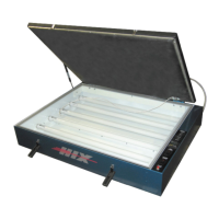
Fluorescent Table Top
Exposure Units
For Customer Service, Call 1-800-835-0606 or
Visit www.hixcorp.com
TT-180D shown
Question and Answer IconNeed help?

Do you have a question about the Hix TT-180D and is the answer not in the manual?

Overview

The HIX TT-180D is a fluorescent table top exposure unit designed for screen printing applications. This owner's manual provides comprehensive instructions for its installation, operation, maintenance, and troubleshooting, ensuring optimal performance and longevity of the device.

Function Description:

The TT-180D serves as a crucial tool in the screen printing process, specifically for exposing photo-sensitive emulsions on screens. It utilizes fluorescent light to cure the emulsion, creating the stencil necessary for printing. The unit is designed to provide consistent and even exposure, which is critical for producing high-quality prints with sharp details. The table top design makes it suitable for various workshop environments, offering a compact yet effective solution for screen exposure.

Important Technical Specifications:

The unit operates on an extension cord, 14 gauge, 3 conductor, with a maximum length of 25 feet (7.62 meters). The exposure area accommodates screens up to 23" x 31". The timer allows for precise control over exposure times, displaying "Minutes" and "Seconds." The unit is designed to be compatible with M&R Trilok pin registration systems, enhancing its versatility and integration into existing screen printing setups. It is crucial to note that the unit emits ultra-violet light, which can cause skin and eye irritation or blindness, necessitating direct exposure to the lamp to be avoided.

Usage Features:

The TT-180D is designed for ease of use, with clear instructions for setup and operation.

  • Receiving & Installation: Upon receiving the unit, it should be carefully uncrate and inspected for any shipping damage. All foreign objects, such as packing material, should be removed. The unit should be placed on a level surface close to the wall circuit to be used. The vacuum pump is shipped separately and needs to be installed. This involves removing the pump from its shipping container, filling it with the supplied oil, and plugging it into the receptacle located on the back of the TT-180 exposure unit. The voltage switch on the pump should be set to the proper voltage (120V or 220V). Finally, the vacuum hose needs to be connected to the fitting on the back right side of the exposure unit lid.
  • Setup: Before operation, the main power source needs to be turned on and the unit plugged in.
  • Loading Screen / Starting Vacuum: To prepare for exposure, the screen is placed in the center of the glass, ensuring it is at least 2" from any edge of the glass to prevent damage to the vacuum blanket rubber. The lid is raised, and the frame is placed in the center of the glass, screen side down. Wooden frames with tape and staples should be taped over to prevent damage to the glass. The bleeder cord is placed inside the frame as close to the frame side as possible. The lid is then closed and latched with the rubber latch-hooks. The vacuum pump power switch is turned "ON," and the blanket is checked for proper draw down.
  • Digital Timer Operation: The main power switch is turned "On," and the timer illuminates. The timer settings can be adjusted using the arrow buttons on the front of the timer face. The timer displays "Minutes" and "Seconds." To program the desired number for the flashing column, the arrow button is pressed for each digit. The counter will loop from 0-9. To change to the next column, the button is pressed until the desired number is reached. Once the new time is entered, the "MD" button is pressed on the face of the timer to lock in the new setting. Failure to press the "MD" button will not "lock" in the new setting. The "Start" button on the control panel initiates the timer and turns on the exposure lamp. The timer counts down, and when it reaches zero, the exposure lamp extinguishes. If the exposure lamp needs to be extinguished before the timer expires, the "RST" button on the face of the timer can be pressed.
  • Determining Optimum Exposure Time: The manual emphasizes the importance of determining the optimum exposure time for the screen being exposed. This procedure involves using an emulsion supplier for an exposure calculator and following their instructions. A step-by-step trial method is provided:
    1. Place cardboard sheets between positive and glass, leaving approximately 2" of positive exposed. After 1 minute, move cardboard approximately 2" more and expose for 1 minute. Then move cardboard approximately 2" more and expose for 1 minute. Repeat at least to 4 minutes. This creates 4 exposure areas of 1, 2, 3, and 4 minutes.
    2. Inspect the newly exposed screen for proper exposure. Underexposed screens will show weak stencil with poor emulsion adhesion and reduced resistance to printing inks and wash up solvents. Overexposed screens will result in loss of fine detail.
    3. Once the proper exposure for the emulsion type is determined, it should be filled in the chart provided in the manual as a ready reference for future use. This procedure should be followed for each new emulsion type, new mesh count, or mesh type (i.e., yellow, orange, white). The procedure should also be followed periodically since the bulb intensity will lessen with age.

Maintenance Features:

Regular maintenance is essential for the TT-180D to ensure its continued efficiency and to prevent costly repairs.

  • Glass Cleaning or Bulb Replacement: To maintain short exposure times, the unit's exposure glass must be kept clean. Dusting is usually sufficient, but if more cleaning is required, a soft cloth moistened with alcohol can be used. A dusty environment will require more frequent cleaning. If exposure times are getting longer or if the lamp fails to operate, the Troubleshooting Chart should be consulted. To clean the back side of the glass or replace bulbs:
    1. Carefully lift the front of the glass from the gasket (leaving the back of the glass resting on its gasket).
    2. Remove the old bulb and insert a new bulb.
    3. Carefully replace the glass as it was before.
    4. Clean the underside and lay it back down carefully. Warning: To lift glass, use flexible (non-rigid) items such as putty knives. If the glass is dropped, it can cause serious injury, so caution is advised. Never use a screwdriver.
  • Vacuum Pump Maintenance: The vacuum pump oil should be changed every 50 hours of usage. The purity of the oil determines the final vacuum level achieved. The recommended vacuum pump oil is VPOQ/VPOP/VPOG. The oil provided with the pump has been specially blended to maintain maximum viscosity at normal running temperatures as well as cold weather starts.
    • Oil Change Procedures:
      1. Ensure the pump oil is warmed up. If not warm, turn the vacuum pump "ON" for 10 minutes.
      2. Make sure the vacuum pump is not plugged in.
      3. Remove the oil drain cap and drain the contaminated oil into a suitable container. Tilt the vacuum pump toward the oil drain port.
      4. Once all the oil has been drained, re-secure the oil drain cap back onto the oil drain port.
      5. Remove the exhaust/oil fill cap and add oil until it is seen in the middle of the oil sight glass. Re-secure the exhaust/oil fill cap.
  • Lid Realignment: The vacuum is sealed under the lid by means of a rubber gasket under the lid frame. This rubber gasket may compress over time. If the vacuum does not occur, the rubber gasket may be compressed. These problems can be alleviated by lowering the hinges.
    • Caution: It is important to do this operation with the lid up, failing to do so could cause injury due to the sudden release of pressure on the gas spring!
    1. Fully open the lid.
    2. Using a pencil, tape, or other suitable indicator, place a mark on the frame of the unit corresponding with a mark on the lower leaf of the hinges.
    3. Using a 9/16" wrench, loosen the four bolts fastening the lower leaf of the hinges.
    4. Let each hinge drop approximately 1/16" using the indicator placed on the hinge in step 2.
    5. Tighten all four bolts securely and test the unit. If this does not work, repeat this process and drop the hinges another 1/16".
    • Warning: Lowering the hinges too much can place excess pressure on the glass and frame of the unit and should be avoided. If the lid is difficult to close or does not stay closed under its own weight, the hinges should be raised.
    • Note: If the blanket fails to pull a vacuum, check the Troubleshooting Chart for possible causes. If it is determined that the blanket has begun to leak, it needs to be replaced. New blanket material can be ordered from HIX Corporation.
  • Repairs: The manual also provides instructions for more extensive repairs, such as replacing aluminum strips and the entire lid assembly.
    1. To begin with the lid in the open position, remove the plastic cap from the lid end of one of the gas springs. While holding the lid, pull the end of the gas spring straight out and off of the ball connector as you continue to manually hold the lid up.
    • Caution: It is important to do this operation with the lid up, failing to do so could cause injury due to the sudden release of pressure on the gas spring!
    1. Remove the vacuum hose from the lid.
    2. Gently lay the lid back down onto the glass. Using two 9/16" wrenches, remove the 4 nuts and bolts holding the lid to the hinges.
    3. Remove the entire lid assembly from the frame and lay it upside down on a flat surface.
    4. Mark from which side of the aluminum strips were located so that they can be replaced in the same location.
    5. Remove all screws from the aluminum strips.
    6. Remove the blanket material and any adhesive still attached to the lid frame.
    7. Lay new blanket material across the lid in the proper orientation, allowing the material to sag down to your working surface.
    8. Seal the rubber to the blanket frame with the included adhesive.
    9. Replace the aluminum strips on the same side that they were removed. Tighten all screws securely.
    • Caution: Over-tightening screws may strip the threads in the lid frame.
    1. Trim any excess blanket material by running a sharp utility knife along the outside of the aluminum frame.

Troubleshooting:

A comprehensive troubleshooting chart is provided to diagnose and remedy common issues:

  • Bulbs do not come on and red light on main power switch is off:
    • Possible Cause: No line power, supply fuse or breaker blown, main breaker is blown, main power switch is defective, outlet is defective.
    • Remedy: Check power source, reset supply breaker or replace fuse, reset unit's main breaker, replace switch, replace outlet.
  • Bulbs do not come on and red light on main power switch is on:
    • Possible Cause: Bulbs are burned out, ballast is bad.
    • Remedy: Replace bulbs, replace ballast.
  • Unit blows fuses or trips Main Power Circuit Breaker:
    • Possible Cause: Check amperage of supply breakers or fuses, shorted ballast.
    • Remedy: Replace supply breakers or fuses with minimum rating of 15 amps, replace ballast.
  • Lamp fails to remain ignited:
    • Possible Cause: Bad lamp, bad ballast.
    • Remedy: Replace lamp, replace ballast.
  • Blanke won't "pull" a vacuum:
    • Possible Cause: Vacuum leak, clean residue off seal.
    • Remedy: Check hose connections to vacuum pump and to blanket frame. Check gasket to glass seal, replace if necessary. Realign lid. Check vacuum pump.
  • Longer Exposure Times:
    • Possible Cause: Dirty glass, worn out bulbs.
    • Remedy: Clean front or back of glass. Replace ALL bulbs.

Warranty:

The HIX TT-180D comes with a warranty that covers manufacturing defects. The warranty period is effective from the date of purchase. Customers are required to fill out a form and attach a copy of their receipt for warranty claims. The warranty covers parts and labor for a specified period, typically one year from the date of purchase, for defects in workmanship and material, except for wear and tear. It also details conditions under which the warranty may be voided, such as improper installation, maintenance, or modifications. The warranty is provided by HIX Corporation, a manufacturer of graphic imaging, commercial food, industrial, and custom drying equipment.

Hix TT-180D Specifications

General IconGeneral
BrandHix
ModelTT-180D
CategoryPrinter
LanguageEnglish