APL-5 Series Limit Switch Box
Installation Operation & Maintenance Manual
Doc No. : HUMG-APL5-16 Rev0 Page 7 / 13
6.2. Mounting limit switch box
Caution ;
Do not attempt to work on limit switch box without first shutting off incoming power
6.2.1. Prior to mounting the limit switch box must be checked for any damage.
6.2.2. Damaged parts must be replaced by original spare parts.
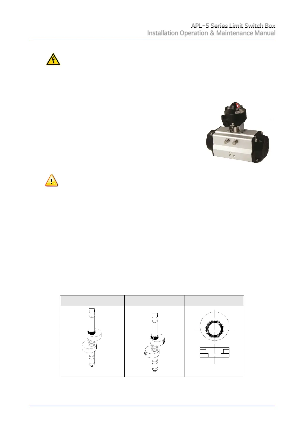
6.2.3. Limit switch boxes are available with a NAMUR shaft that enables direct attachment to
actuator pinion without a coupler. These shafts feature a 4mm wide tang that engages the
4mm slot in NAMUR actuators.
① Check to be sure the drive slot on the top of the actuator
and the shaft of switch box are the same direction.
② Insert the shaft of switch box carefully into the
mounting bracket.
③ Tighten the bolts enclosed in a box using a proper tool.
④ Check the connection of shaft being assembled
correctly.
6.3. Cam setting
Note :
Basically, cams shall be set by manufacturer before shipment.
6.3.1. The colour of cams harmonized with position indicator help us to set the cams easily
without wiring diagram. Cams shall be easily set without tool. APL series cams are splined
and can be setting lift up or push down the cam from gear by hand in a seconds without
setting tools. Self-locking, spring loading make never slip out of adjustment.
6.3.2. Loose the captive cover bolts with an applicable tool. (L-Hex. Wrench recommended)
6.3.3. Turn the cover counter clockwise to open carefully.
6.3.4. Open cam setting
① Electric power or air supply of valve actuator on to operate the actuator fully open
② Lift the bottom yellow cam up and rotate it until the switch is activated.
③ And then release it. Cam shall be back into a stable position by itself.
6.3.5. Close cam setting
① Electric power or air supply of valve actuator off to operate the actuator fully close
② Push the upper cam down and rotate it until the switch is activated.
③ And then release it. Cam shall be back into a stable position by itself.
 Loading...