APL-5 Series Limit Switch Box
Installation Operation & Maintenance Manual
Doc No. : HUMG-APL5-16 Rev0 Page 8 / 13
6.4. Wiring
Danger ; HAZARDOUS VOLTAGE. No electrical power should be connected until all
wiring and limit switch adjustments have been completely.
6.4.1. [Open circuit before removing cover, and seal required within 50mm
(2 inch) of the enclosure by CSA ---- 15 r0]
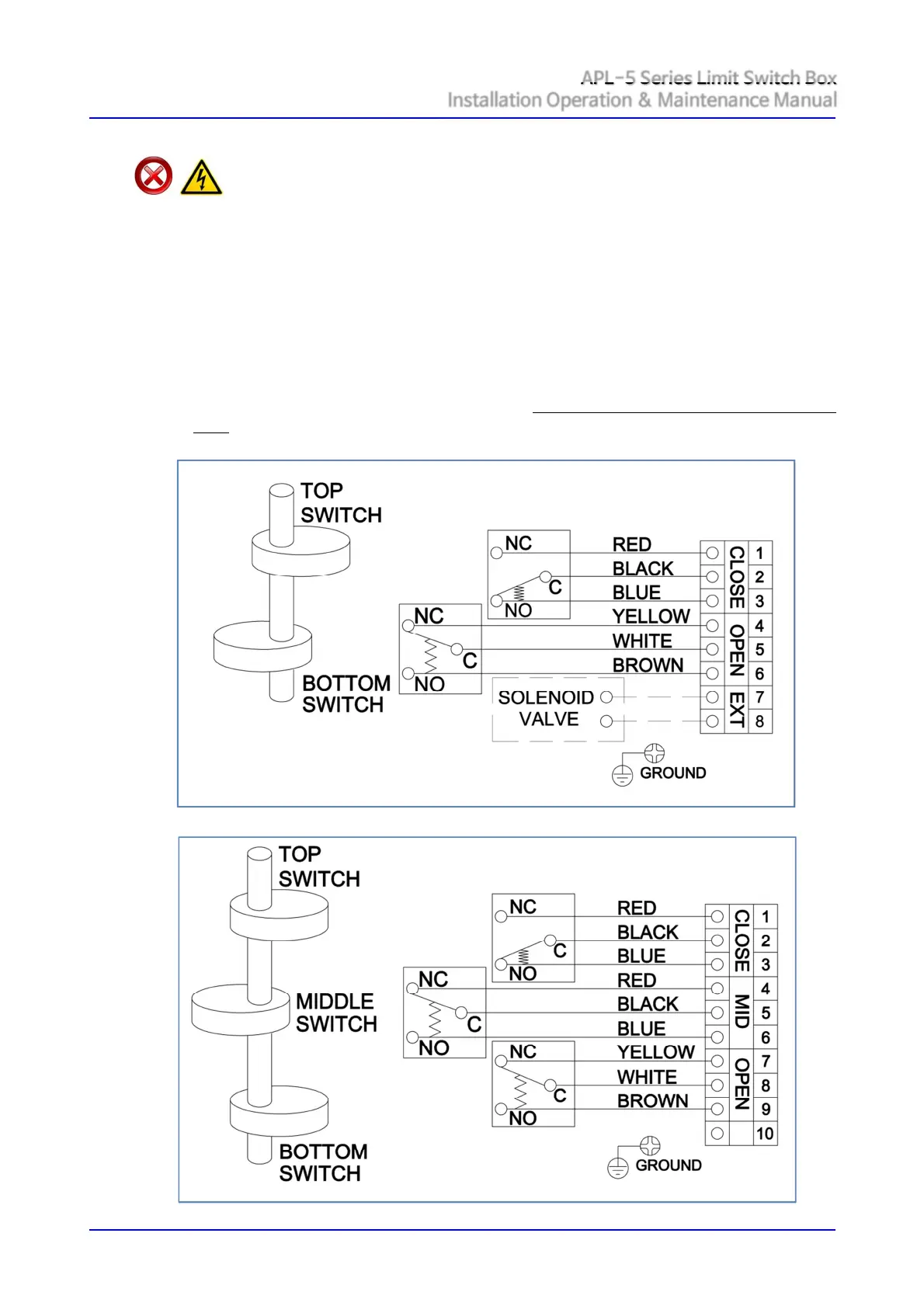
6.4.2. APL limit switch box enclosure feature prewired switches. All user connections are made at
a numbered terminal strip. A wiring diagram, located inside the cover, indicates which
terminal numbers correspond to switch contacts, such as normally open (NO), normally
closed (NC), etc. Follow the wiring diagram and electrical code to connect the switches to
your system.
6.4.3. Solenoid valve may also can be wired through the APL enclosure. Two auxiliary terminals
are included as standard.
6.4.4. APL limit switch box has two cable entries on the body and supply a blanking plug not a
cable gland which meet the type of protection. Cable gland shall be applied by installer or
user.
① Mechanical Switch (2 SPDT)
② Mechanical Switch (3 SPDT)
 Loading...