© 2020 HM Electronics, Inc. All rights reserved. 400Gxxx.
InstallatIon
1. Survey the premises with store manager to determine
the optimal mounting locations for each component.
Take into consideration:
• Cable lengths for the hardwired components.
• Base Station accessibility to all crew members and in
an area free from obstructions.
• The Base Station mounting height should be be-
tween 4 feet (122 cm) and 5 feet (152 cm) from the
floor (see Fig. 1.1). Note: Mounting height should
also take into consideration personnel with disabili-
ties.
• Choosing a good Remote Transceiver mounting
location is critical (see Component Notes, and Step
5 with Fig. 1.3, and 1.4).
HME
BASE STATION
SIGNAL STRONGEST
DIRECTLY IN FRONT
OF REMOTE TRANSCEIVER
Fig. 1.1
2. Set up and connect power to the AC70 Battery Charger.
Insert batteries to begin charging. Up to four batteries
can be charged at one time. See Component Notes for
more information.
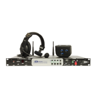
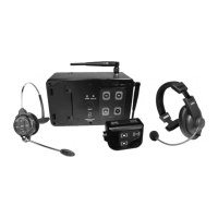
NEXEO HDX™ WIRELESS SYSTEM
QUICK REFERENCE INSTALLATION GUIDE
3. If you are replacing an existing HME product, placing the
Base Station close to the Base Station you are replacing
will enable you to use the existing wires/cables without
having to route new wires. However, verify the wires/
cables are in good condition before using. Open the
Base Station and mark the mounting location on the wall
through the four mounting holes at each corner inside
the Base Station (see Fig 1.2). Mount the Base Station
using the hardware provided.
Remote
Module 1
Remote
Module 2
Remote
Module 3
Remote
Module 4
Ethernet
DC +
DC -
GND
Micro
USB
J200
J600
J201 J800 J801
J802
J805
J804
J803
J2003
J3000
J4500 J4501
J?400
J3200
J3400
J3600
J3800
1
1
1
1
1 1 1
1
1
1
1
Serial
Debug
USB
J?301
J?300
J1
Latches
Mounting
Holes
Base Station
opened
PCBA
Fig. 1.2
4. Also mount the Base Station power supply. Mark the
mounting location on the wall through the mounting
holes on each side. Mount the power supply using the
hardware provided.
5. Critical Step: Loosely mount the Remote Transceiver
in an optimal location (until range tested with a roving
headset using the Installation Wizard via the Base Station
in steps 9 & 10). For example, notice Fig. 1.3 and 1.4,
they show two different store layouts with specific target-
ed areas where the headsets are primarily used (the blue
areas are those needing coverage). Each store required
the Remote Transceiver (represented by the small blue
rectangle) to be mounted in an optimal location to pro-
vide best coverage resulting in two different mounting
locations unique to the store’s need (see “Component
Notes” on page 3 for more details on placement).
Fig. 1.3
INDOOR
SEATING AREA
OUTDOOR
SEATING AREA
KITCHEN
SHELVING
SHELVING
APPLICANCES AND
FOOD PREPARATION
MENU &
SPEAKER POST
STORAGE
COUNTER
SERVICE WINDOW
BASE
STATION
REMOTE
TRANSCEIVER
DRIVE-THRU LANE
Fig. 1.4
Present
Window
Appliance and
Food Preparation
Pay
Window
Oce
KITCHEN
Storage
Counter
Wait Areas
1 2
Sidewalk
Parking Lot
Mobile Orders
1 2
Menu &
Order
Point
Drive-Thru
Lane
Entrance
Dining/Seating Area
REMOTE
TRANSCEIVER
BASE
STATION
Typical Single Lane drive-thru store layout
QRS Aerial/Plan View
1
3
4
5
2