Do you have a question about the HMS Anybus HMS-EN2MB-R and is the answer not in the manual?
Describes how to install and configure the linking device.
Explains numbering, bullet points, and user interaction element conventions.
Lists other documents relevant to the linking device and its protocols.
Tracks versions, dates, and descriptions of changes made to the document.
Lists registered trademarks and proprietary names associated with the product.
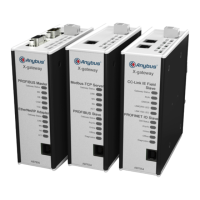
Highlights key capabilities of the EtherNet/IP to Modbus-TCP linking device.
Explains how the linking device ensures data consistency across network connections.
Details data exchange through buffers between the linking device's network interfaces.
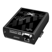
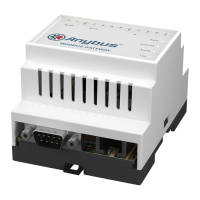
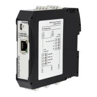
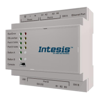
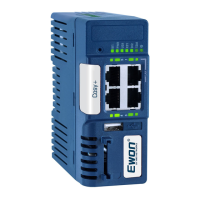
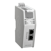
Provides a visual overview of the linking device, identifying its connectors and components.
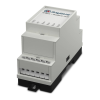
Describes methods for physically installing the linking device, including DIN-rail and wall mounting.
Details the pinout and function of the power connector for supplying power and grounding.
Lists the pin assignments for the EtherNet/IP and Modbus-TCP RJ45 connectors.
Describes the USB port used for firmware upgrades and PC connectivity.
Outlines the step-by-step process for configuring the linking device using Studio 5000.
Lists the prerequisites necessary for the configuration manager to function correctly.
Introduces the tag editor as the foundation for configuring the linking device.
Details system requirements and considerations for configuring Modbus-TCP servers and transactions.
Provides a detailed guide with steps to create a basic configuration using Studio 5000 software.
Explains how the tag editor generates and manages tags based on Modbus-TCP client configuration.
Lists the rules that automatically generated tags must adhere to for process data mapping.
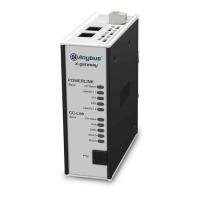
Describes the meaning and indication of the various status LEDs on the linking device.
States that EMC compliance testing was conducted according to the relevant directive.
Provides a procedure for replacing a faulty linking device, emphasizing configuration backup.
Outlines the functionality and usage of the SD card for configuration backup and copying.
Explains I/O mapped data as cyclic data exchanged at high transfer rates using implicit messaging.
Describes parameter data exchange as acyclic, used for setting or changing parameters.
Explains how the PLC retrieves a live list of transaction statuses on the Modbus-TCP network.
Holds information about transactions between Modbus-TCP servers and the linking device client.
Lists Modbus exception codes returned by a Modbus-TCP server during transaction failure.
Lists supported Modbus-TCP functions, their codes, directions, and buffer associations.
Describes functions available in the File, Edit, Tools, and Help menus of the configuration manager.
Details options for selecting, deselecting, and converting tags to arrays within the tag editor.
Presents the structure of configuration and status pages, including headline, navigation, and content sections.
Correlates the operation modes of the Modbus-TCP and EtherNet/IP networks.
Explains enabling/disabling authentication and setting credentials for configuration protection.
Guides the configuration of the Modbus-TCP client side of the linking device.
Describes how to configure Modbus-TCP servers, including adding and editing server settings.
Details how to configure the EtherNet/IP adapter interface settings for the linking device.
Lists various tools for managing the linking device, including Apply Changes, Reboot, and Backup/Restore.
Provides identification and general information about the module, including revision and vendor details.
Offers a messaging connection point for clients to address services to any object class or instance.
Holds Process Data sent/received by the host application over a single connection.
Manages connections for I/O data transfer, defining connection types and transport details.
Manages network topology and status, indicating linear or ring configurations and faults.
Configures Quality of Service parameters, including 802.1Q tagging and DSCP values.
Configures the TCP/IP network interface, grouping IP-related settings like address, mask, and DNS.
Maintains link-specific counters and status information for an IEEE 802.3 communications interface.
Specifies the need for functional earth connection via DIN-rail for proper EMC behavior.
Details the required regulated 24 V DC power source and typical power consumption.
Provides operating and non-operating temperature ranges and relative humidity guidelines.
Provides essential precautions for handling and using SD cards with the linking device.
Outlines the steps for initializing and configuring the linking device using an SD card.
Describes how configurations are automatically saved to Studio 5000, PLC memory, and the SD card.
Addresses potential SD card write failures and provides troubleshooting steps.