Do you have a question about the HMS Anybus X-gateway and is the answer not in the manual?
JMI allows monitoring and control of J1939 data via Modbus RTU.
Lists required hardware and software for using the X-gateway.
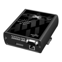
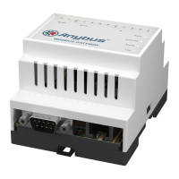
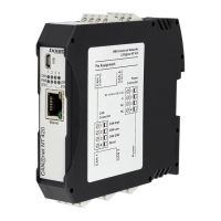
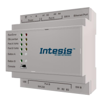
Details connectors (15-pin D-Sub, 25-pin D-Sub) and LEDs for status.
Wiring standards, explosion hazards, terminal torque, temperature, wire type.
Describes the 15-pin D-Subminiature connector for power and network.
Describes the 25-pin D-Subminiature connector for PC connection.
BWConfig is a Windows application for configuring the JMI module.
Parameters for controlling the Modbus serial interface behavior.
Parameters for J1939 address management and network options.
Defines content and format of the J1939 Input/Output tables.
Modbus RTU serial protocol, module acts as a Modbus slave.
Lists Modbus function codes supported by the interface.
How I/O data tables are addressed using standard Modbus addressing.
Register addresses for retrieving diagnostic information from the JMI.
PLC on Modbus needs J1939 data; controller sends data to J1939.
Defining input data points to map J1939 message data to Modbus registers.
Defining output data points to produce PGN messages on J1939.
Process of bringing the module online with a unique J1939 network address.
How messages are assembled from output data points and transmitted.
How JMI handles different J1939 messages like Address Claimed and Requests.
Monitoring DM1 (active) and DM2 (previously active) diagnostic messages.
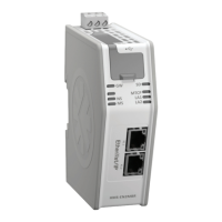
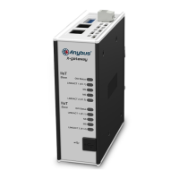
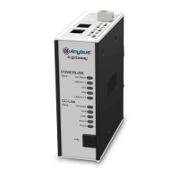
Group of LEDs on the front indicating module and network interface status.
States and descriptions for the J1939 network status LED.
States and descriptions for the Modbus network status LED.
General and error status codes displayed by the configuration tool.
DC power requirements and operating voltage.
Maximum sizes for Input/Output tables and PGN limits.
Communication mode, serial interface parameters.
Pin definitions for the 15-pin D-Sub connector used for power and networks.
Pin definitions for the 25-pin D-Sub connector used for configuration.
Contact information for HMS Sweden (sales and support).
Contact information for HMS North America (sales and support).
Contact information for HMS Germany (sales and support).
| Category | Gateway |
|---|---|
| Protection Class | IP20 |
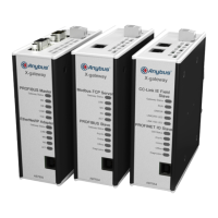
| Model | HMS Anybus X-gateway |
| Manufacturer | HMS Networks |
| Supported Networks | PROFIBUS, PROFINET, DeviceNet, EtherNet/IP, Modbus, CANopen, CC-Link |
| Power Supply | 24 V DC (typically 18-30 V DC) |
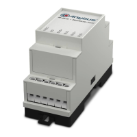
| Mounting | DIN rail |
| Operating Temperature | 0 to +55°C (32 to +131°F), with variations depending on the specific model. |
| Relative Humidity | 5% to 95% (non-condensing) |
| Certifications | CE, UL |
| Protocol Conversion | Yes, bidirectional protocol conversion between different industrial networks |