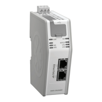
Anybus X-gateway Modbus-TCP - PROFINET
INSTALLATION SHEET
HMS Industrial Networks AB
Web: www.anybus.com
Tel: +46 35 172900
E-mail: info@hms.se
SP1330, rev 2.01, Mar 2012. AB9007. www.anybus.com
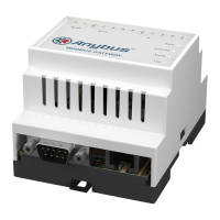
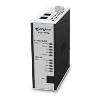
Module Front
Top View
Power:
(+) +24 V DC
(-) GND
(A) PE
SD card slot:
Modbus-TCP Connector:
Pin no Description
1 TX+
2 TX-
3 RX+
6 RX-
4, 5, 7, 8 Termination
18
Bottom View
(Front)
X2.1
X2.2
X3
Further informa on and documents about this product can be found at
the product pages on www.anybus.com.
1
2
3
5
6
7
8
4
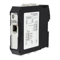
PROFINET
Connector:
Pin no Description
1 TX+
2 TX-
3 RX+
6 RX-
4, 5, 7, 8 Termination
18
USB port:
Connect a PC to the USB port
for fi rmware upgrades.
X1.1
X1.2
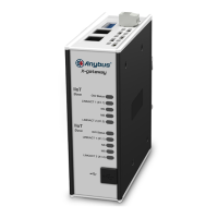
LEDs: X-gateway and Modbus-TCP Network
No Name Indication Meaning
(GW)
Gateway Status
Off
Alternating red/green
Flashing green
Green
Flashing red
Red
Power off
Missing confi guration
Idle
Running
Invalid confi guration
Fatal error
(SD)
SD Card Status
Green
Flashing red
Accessing SD card
Failure
(MTCP)
Modbus-TCP Status
Off
Green
Flashing red
Red
No Modbus-TCP network communication
Communicating with Modbus-TCP network
Transaction error or timeout
Fatal error
(LA1, LA2)
Ethernet Link 1 & 2
Off
Flashing green
Flashing yellow
No link
Receiving/transmitting Ethernet packets
at 100 Mbit
Receiving/transmitting Ethernet packets
at 10 Mbit
No Name Indication Meaning
Not used - -
(NS)
Network Status
Off
Green
Flashing green
No connection
Online (RUN): Connection established, IO
controller in RUN state
Online (STOP): Connection established,
IO controller in STOP state
(MS)
Module Status
Off
Green
Green, two fl ashes
Red
Red, one fl ash
Red, two fl ashes
Red, three fl ashes
Red, four fl ashes
Not initialized
Normal operation
Used by engineering tools to identify the
module on the network
Fatal error
Confi guration error
IP address error
Station name error
Internal error
LEDs: PROFINET Network
1
2
3
4
5
6
7
8
Installation and Startup Summary
• A ach the X-gateway to the DIN-rail.
• Connect the module to the PROFINET network.
• Connect the module to the Modbus-TCP network.
• Turn on the module (+24 V DC).
• Download IPconfi g from www.anybus.com to a PC.
• Connect the PC to the module via one of the Modbus-TCP con-
nectors (Ethernet crossover cable not necessary). Use IPconfi g
to iden fy the IP address of the module on the network using its
Modbus-TCP MAC address (found at the bo om of the module).
• Start a web browser (IE 7.0 or 8.0), enter the IP address and con-
nect to the X-gateway’s web interface.
• Confi gure the module using the web confi gura on pages.
• Include the Anybus X-gateway GSD fi le in the PROFINET confi gura-
on tool (download the GSD fi le from www.anybus.com).
• Confi gure and start the PROFINET network.
Technical Details
• Power supply:
24 V DC (-15% to +20%).
• Power consump on:
Maximum power consump on is 300 mA @ 24 V DC.
Typical power consump on: 150 mA @ 24 V DC.
• Surrounding temperature
70 degrees C @ 225 mA @ 24 V DC.
• Protec ve Earth (PE):
Internal connec on to PE via DIN-rail or, if the DIN-rail can not be
used, via the power connector.
Note: Make sure the DIN-rail is properly connected to PE.
For maintenance and support, contact the HMS support department.
Contact informa on is available at the support pages on
www.anybus.com.