Do you have a question about the HMS Intesis KNX - Hisense VRF and is the answer not in the manual?
Describes the integration of Hisense VRF systems into KNX home automation systems using the gateway.
Explains how Intesis monitors Hisense VRF signals and updates KNX status on value change.
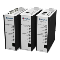
Details the capacity of the Intesis gateway in terms of supported indoor units and provides order codes.
Describes how Intesis KNX connects to the KNX TP-1 bus and functions as a KNX device.
Explains the KNX properties for group objects, including DPT, Group, and flags like R, Ri, W, T, U.
Details the procedure to power up the device and important safety recommendations.
Explains connecting the Hisense H-Link bus to the Intesis device's Port B.
Describes connecting the KNX TP1 bus to the gateway's Port A, highlighting polarity.
Outlines two methods (Ethernet and USB) to connect to the PC for configuration and monitoring.
Lists requirements for KNX installation, Hisense AC, and necessary auxiliary materials.
Introduces Intesis MAPS, a Windows compatible software for configuring Intesis KNX gateways.
Introduces Intesis MAPS, a Windows compatible software for configuring Intesis KNX gateways.
Details how to configure Intesis connection parameters using the 'Connection' button in MAPS.
Explains how to use the Configuration tab in MAPS, covering General, KNX, and Hisense parameters.
Covers device configuration, operating modes, fan speed, vane position, and temperature sensor settings for the KNX interface.
Details setting parameters for connecting and configuring Hisense units within Intesis MAPS.
Lists all available KNX objects, descriptions, DPT, and flags in the signals tab of Intesis MAPS.
Details the steps for saving the project and sending the configuration file to the Intesis gateway.
Describes the diagnostic tools and viewers available in the Configuration Tool for troubleshooting.
Provides a step-by-step guide for installing and setting up the Intesis gateway and configuration.
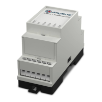
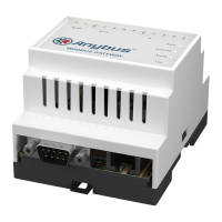
Describes the enclosure material, dimensions, color, and mounting options for the gateway.
Details wiring specifications and power consumption/voltage requirements for the device.
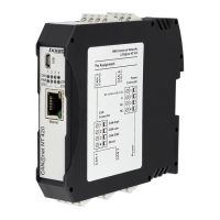
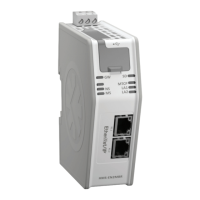
Lists specifications for Ethernet, Port A (KNX), Port B (H-Link), and Console connections.
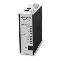
Explains the function of switches and the various onboard LED indicators on the gateway.
Provides detailed diagrams and measurements of the Intesis gateway's physical dimensions.
Recommends available space for installation, considering external connections.
Provides a link to a list of Hisense unit model references compatible with the gateway.
Lists possible error codes for indoor and outdoor units, their categories, content, and leading causes.
Lists communication objects for general signals, operating modes, fan speed, and vane position.
Details communication objects related to outdoor unit signals such as temperature, pressure, and compressor status.
Details communication objects for indoor unit control and status, including fan speed and vane position.
Lists communication objects for temperature readings, unit error codes, and filter status.
Lists communication objects for system information, remote control, dehumidification, and other status indicators.