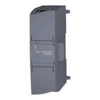
CM CANopen Module for SIMATIC S7-1200
Doc.Rev. 1.00
Chapter 4
4. Installation
The mounting and configuration of the CM CANopen Module for SIMATIC S7-1200 is done following
these steps:
1. Mounting
2. Configuring the SIMATIC S7-1200 PLC to use the module (See “SIMATIC S7-1200 PLC Con-
figuration” on page 10)
3. Setting the parameters of the module (See “SIMATIC S7-1200 PLC Configuration” on page 10)
4. If in a CANopen operation mode, configuring the CANopen network, including the module (See
“CANopen Network Configuration” on page 12)
The following items are needed to perform the installation:
• TIA Portal V11, SP2 or later
• HSP (configuration file) for the module
1
• CM CANopen Configuration Studio
• Function blocks (optional)
1
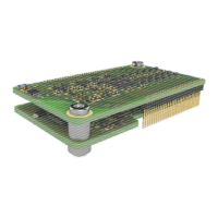
4.1 Mounting
The CM CANopen Module for SIMATIC S7-1200 is designed to be connected di-
rectly to a SIMATIC S7-1200 PLC.
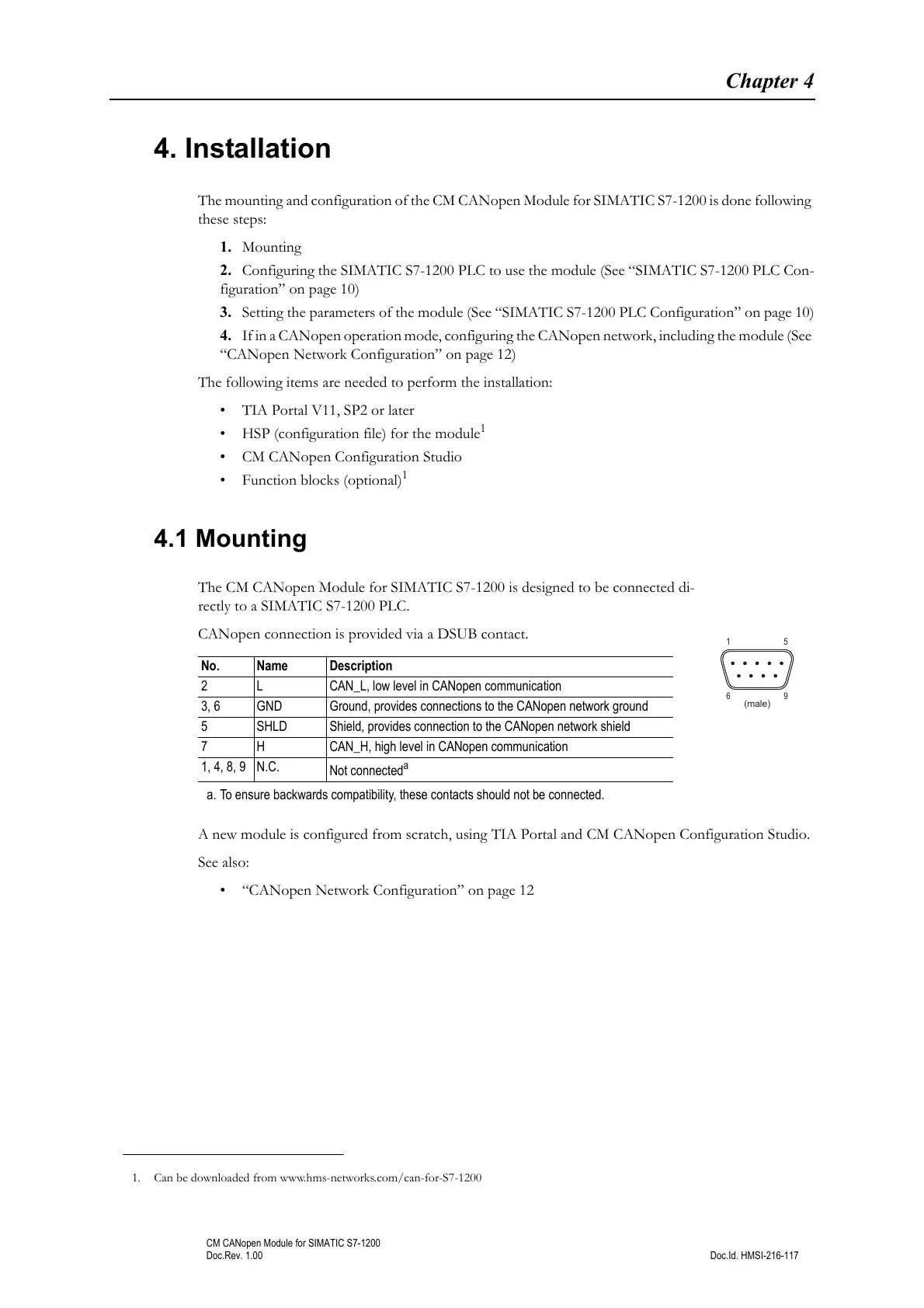
CANopen connection is provided via a DSUB contact.
A new module is configured from scratch, using TIA Portal and CM CANopen Configuration Studio.
See also:
• “CANopen Network Configuration” on page 12
1. Can be downloaded from www.hms-networks.com/can-for-S7-1200
No. Name Description
2 L CAN_L, low level in CANopen communication
3, 6 GND Ground, provides connections to the CANopen network ground
5 SHLD Shield, provides connection to the CANopen network shield
7 H CAN_H, high level in CANopen communication
1, 4, 8, 9 N.C.
Not connected
a
a. To ensure backwards compatibility, these contacts should not be connected.