REMOVAL AND REPLACEMENT PARTS
SHARPENER
Disconnect the
electrical power to the machine and
follow lockout / tagout procedures.
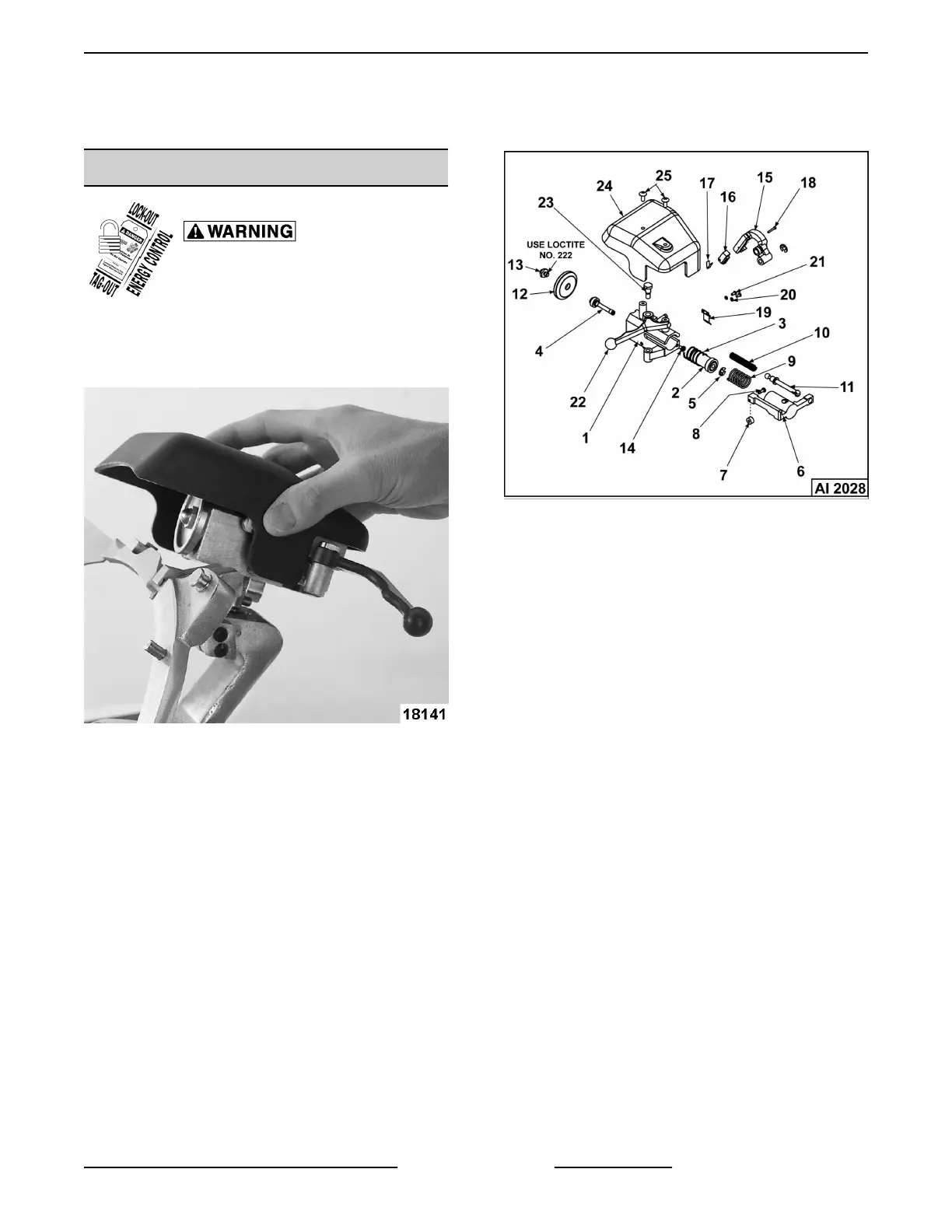
Sharpener - Removal
1. Lift up to remove sharpener from sharpener
mount.
Fig. 3
Sharpener - Disassembly
NOTE: Remove only those parts required to access
part(s) being replaced.
Fig. 4
NOTE: Refer to graphic #AI 2028 for disassembly.
1. Remove two screws (25) to remove cover
assembly (24).
2. Remove screw (23) from housing assembly (1)
to remove sharpener handle (22).
3. Squeeze together split end of push rod (11) and
push it from actuator (6).
A. Remove push rod (11) by freeing rod ball
from socket on truing arm (15).
B. Squeeze together split end of rod (11) and
pull truing arm spring (10) from rod.
4. Remove screw (14) to remove actuator (6) and
spring (9) from housing assembly (1).
5. Place a screw driver blade in end of grinding
wheel shaft (4). Remove (R.H.) retaining screw
(13) from shaft to remove grinding wheel (12) and
allow plunger (2) and spring (3) to be removed
from housing assembly (1).
NOTE: When reinstalling retaining screw (13) Loctite
No. 222 must be used on threads.
6. Remove retaining ring (5) and pull grinding wheel
shaft (4) from plunger (2).
NOTE: The sleeve bearings in plunger are not
serviceable. Plunger and bearings must be replaced
as an assembly (2).
HS Series Slicer - REMOVAL AND REPLACEMENT PARTS
Page 9 of 85 F45476 Rev. A (0313)
 Loading...