FINAL ASSEMBLY AND COVERING
c 1
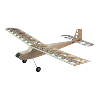
Place the wing assembly upside down on the
bench and place the rear wing mount (RWM)
over the magnets. Place one of the 1/8” x 1/4”
magnets in each of the holes provided. Make
sure the magnets attract. Use a felt tip marker
to mark the top of each magnet and RWM.
The marked side of each magnet and RWM
must be installed face down in the fuselage.
Without removing the magnets, glue them to
RWM.
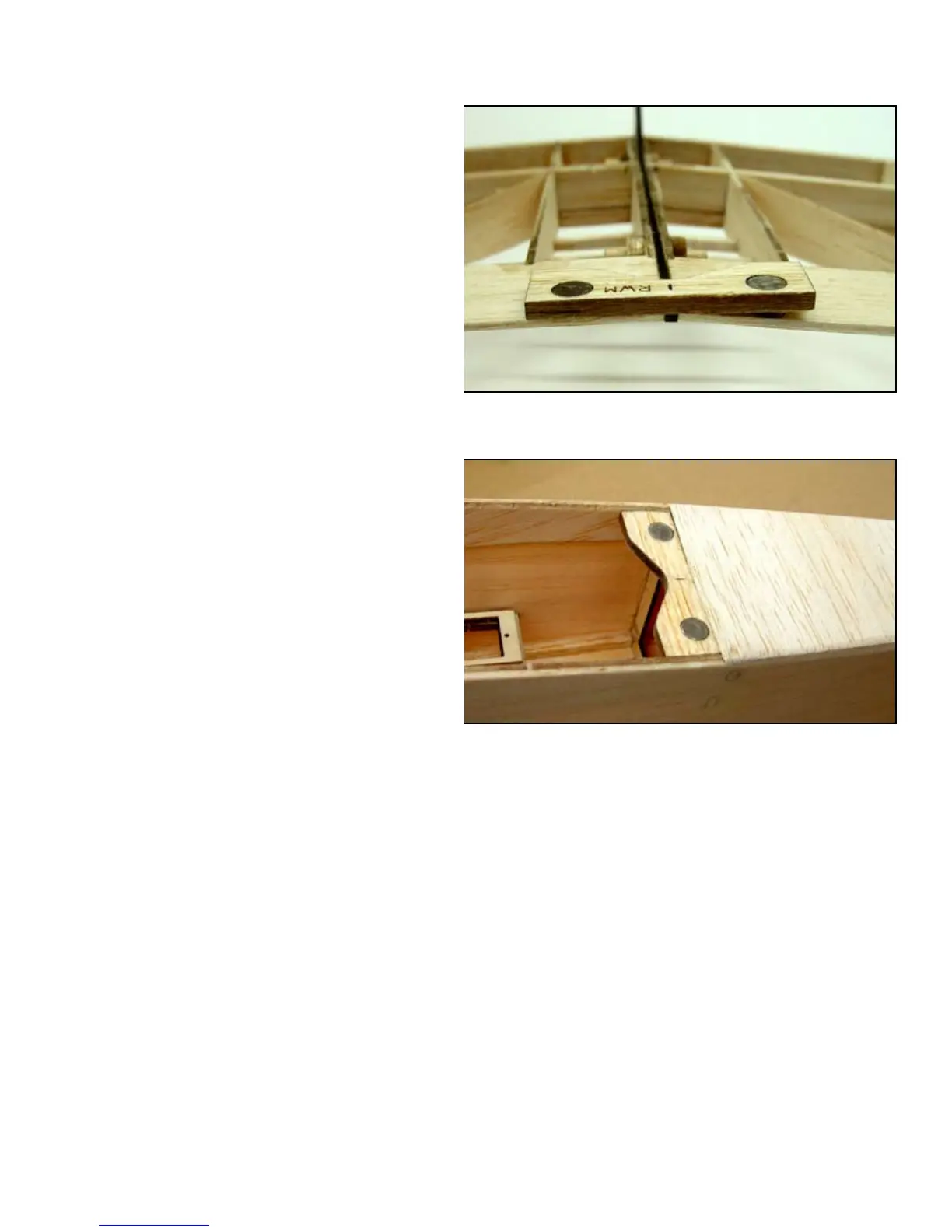
c 2
Glue the RWM and magnet assembly into
the fuselage just in front of F3 as sown in the
photo. remember the side that was up on the
wing must face down in the fuselage.
ABOVE: RWM is placed over the wing magnets and the 1/4” mag-
nets are installed with the correct polarity. This assembly is then
installed into the fuselage (BELOW) with the marked side down.
For lightest weight and best ying, cover your model with a lightweight covering designed for park y-
ers. This will not only yield a better ying model but also be much less likely to produce warps in the
light weight structure.
Cover the fuselage and empennage separately and assemble them after they have been covered. Support
the fuselage at on the bottom (not on the gear) and install the stabilizer. Check that each trailing edge tip
is the same distance from the center of F2 and that both tips are the same distance off of the bench. When
these conditions have been met, glue the stabilizer in place. Remove the covering from the area where
the vertical n will mount on top of the stabilizer and glue the vertical n to the stabilizer in the slots
provided. Use the building square to insure the n is at 90 ° to the stabilizer.
Hinge the moveable surfaces with hinge tape or covering material. Install the elevator horn (EVH) on the
left elevator and the rudder horn (RUH) on then right side of the rudder in the slots provided.
8
 Loading...