9
WHEEL ASSEMBLY
c 4
c 3
c 2
c 1
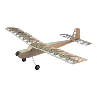
Install a 3/32” x 3/8” brass tube into one of
the wheel covers (WC). Place a wheel hub
(WH) down over the brass tube and glue it
to the wheel cover.
Use a contact adhesive such as 3-M 77 spray
glue to spray one side of all four foam tires.
Slide one of the tires down over the wheel
hub with the glue side up. Slide another tire
down over the wheel hub with the glue side
down. This will become one tire. Repeat this
process for the second tire.
Glue the tire assembly to the wheel cover as-
sembly with thick CA. Then glue on the re-
maining wheel cover with thick CA.
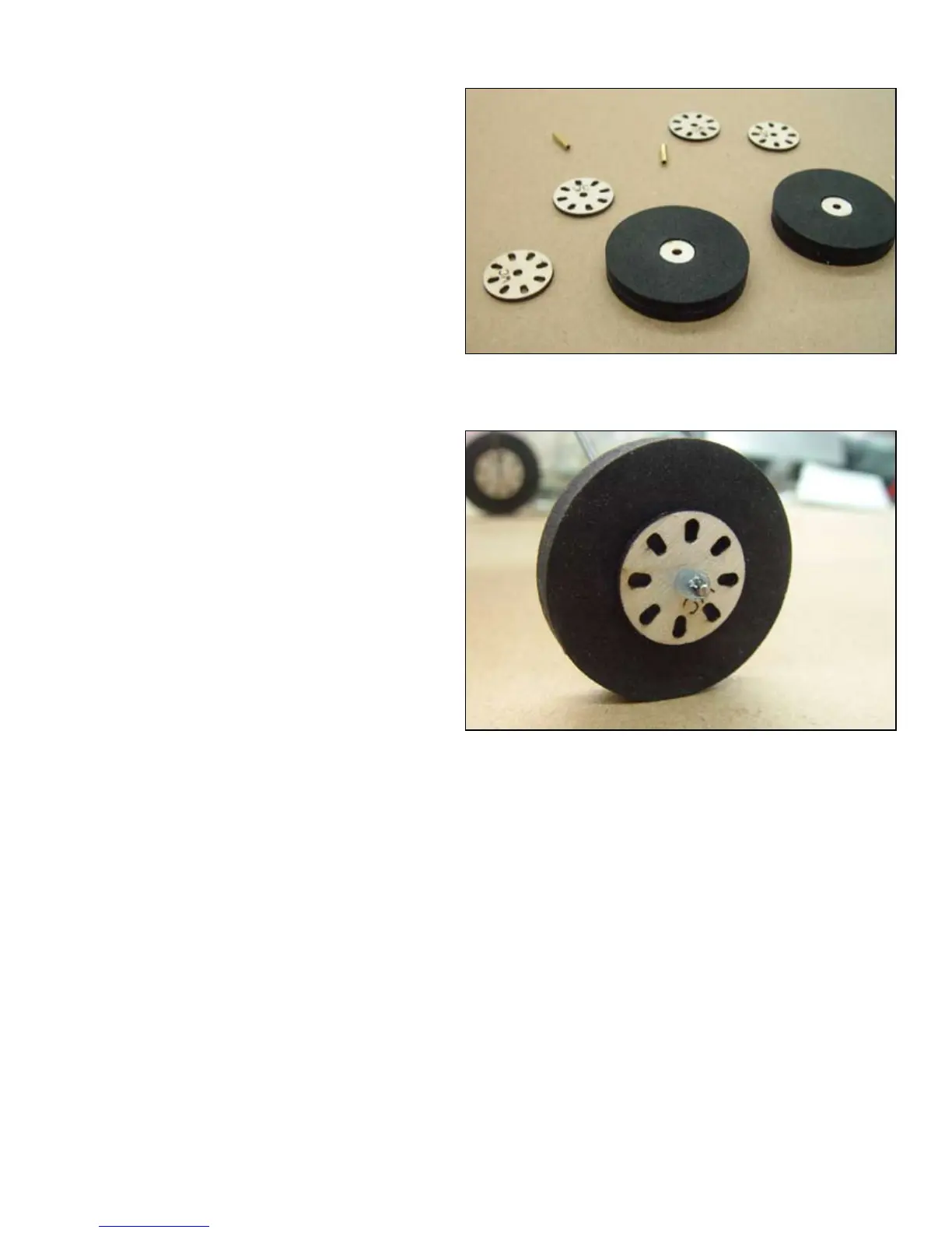
Cut four pieces of silicone fuel tubing about
3/32” long. Place one of these on each axle
of the landing gear just short of the bend.
These will be the inner wheel collars. Place
the wheel on the axle and then another piece
of fuel tubing. Use a drop of thick CA to
secure the outer collar to the axle.
ABOVE: The wheel components laid out ready for assembly.
BELOW: the assembled wheel installed on the axle. Note the bead
of CA used to retain the silicone wheel collar.
BALANCE
Almost as important as the CG, is the lateral balance. Make a piece of string with about a 10” loop in it.
Place the loop around the wing and tape the string dead center on top of the wing. Now ip the wing over
and let it hang from the string loop. Observe the heavy wing and add weight to the high wing until the wing
hangs level. Glue this weight permanently to the high wing.
If at all possible, obtain the correct CG by moving the battery or receiver without adding weight. If addi-
tional weigh is required, place as far forward or aft as possible to minimise the amount required. In most
case additional weight will not be necessary.
Set your surface throws up for 5/8”left and right on the rudder and 1/2” up and down on the elevator.
 Loading...