c 4
Glue F2 in the same manner.
2
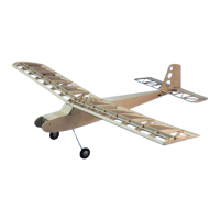
ABOVE: The right fuselage side has F1, F2, F3 and the servo tray
installed and is ready for the left side to be installed.
c 5
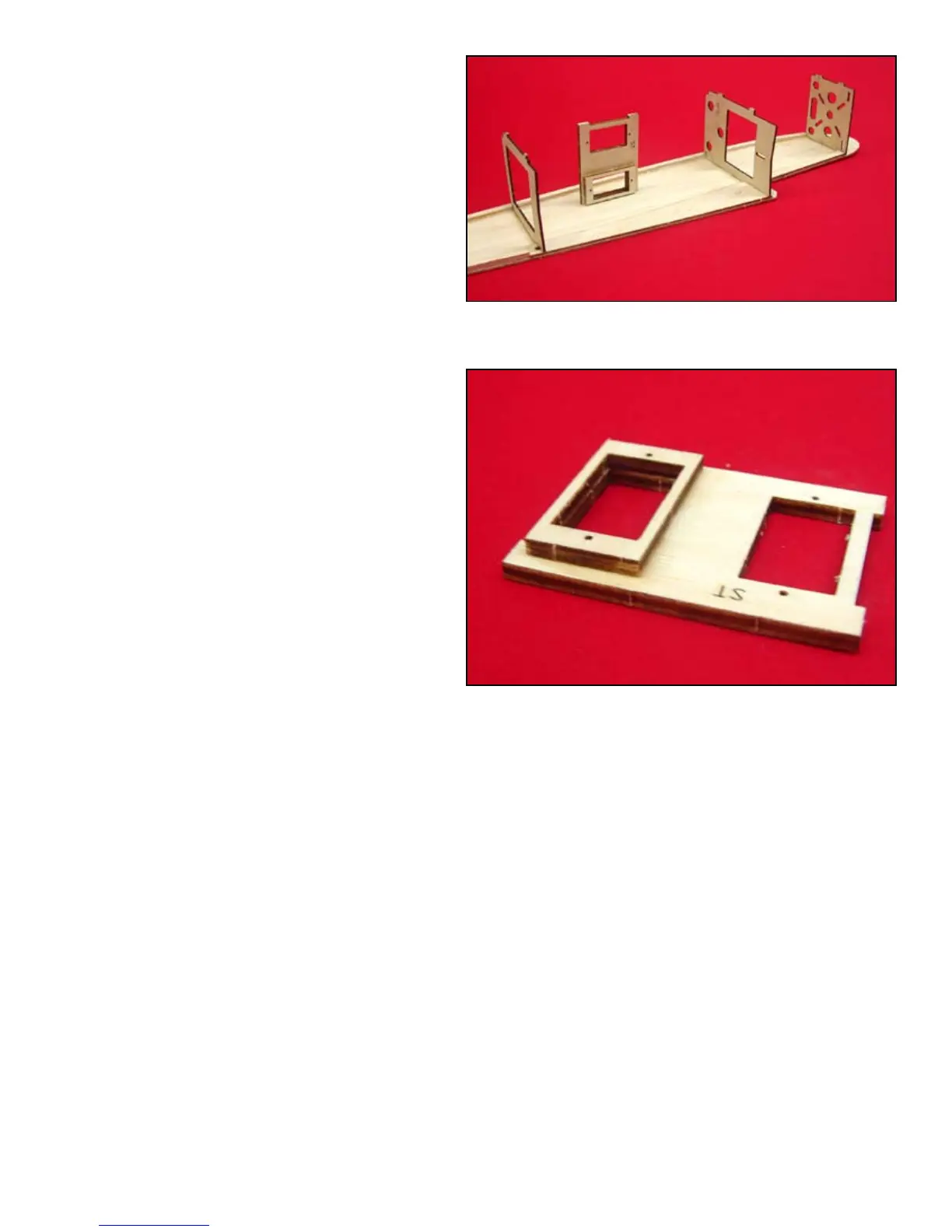
The servo tray (ST) requires some prefabrica-
tion before installing it into the fuselage. To
facilitate a straight through criss cross push-
rod installation, one servo is elevated by 1/8”
by installing ST-B to one of the servo open-
ings. It makes no difference which one but
ST-B must be on top of the servo tray when
installed. Glue ST-B to ST and then install
the ST assembly to the fuselage side. Use the
square to insure it is at 90º to the fuselage
side.
c 6
Glue F3 to the fuselage side in the same man-
ner.
c 7
Test t the left fuselage side to the right side
assembly. When satised that everything will
t, glue the two sides together.
ABOVE: One of the servo openings is raised by 1/8” to accom-
modate a straight linkage between the servo and the moveable
surfaces. This simplies the push rod assembly and installation.
c 8
Glue a 1/8” square balsa brace to the back of
F1 to support the bottom sheeting when in-
stalled.
c 9
Use heavy thread and CA to bind the landing
gear to the landing gear mount (GM) in three
places. Keep the threads neat and compact.
Note the three holes in F2, they will allow the
threads to protrude through F2 without inter-
fering with the t of F2 and GM. Glue the GM
assembly to F2.
c 10
Temporarily pull the tail section together.
Note that both sides bend the same. If not, cut
saw kerfs in the stiff side to weaken it. This
will make it easier to nish installing the bot-
tom sheeting.
 Loading...