ring (part no. 26), using the fourth hole
from the top. (Fig. 28)
5w.. ",,"
J . '"
. " ~~ "
Fig. 28
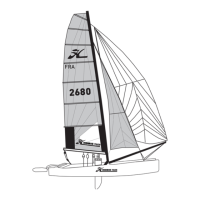
24. Now slowly release the main halyard. Let
about 2 feet of the halyard line run through
the sheave and tie the rest securely to the
mast rotation bar or the mast base as in
step 23 of this chapter. The angle of the
mast will shift from left to right as the load
is shifted from the main halyard to the side
bridle wire.
25. Locate the other bridle wire. Clear the bri-
dle of any wraps and attach the cleared
bridle to the right ten-hole adjuster you
installed during step 6 of this chapter VI.
Insert the clevis pin and ring (part no. 26),
using the fourth hole from the top.
26. Release the twist shackle endot1temain
halyard from the right ten-hole adjuster.
27. Secure the shackled end of the main hal-
yard to the boat to prevent it from slipping
to the top of the mast accidentally.
-16-
 Loading...