35X1 MD80-S Manual 1.0 en
3. Power the Audio Module by either connecting the
AC power cable to the power distribution panel or by
powering an already established power line to the
Audio Module, e.g. by connecting a circuit breaker.
When powering on the Audio Module, the following
startup events take place over several seconds:
a. When mains power is detected, the “POWER”
LED on the Electronics Package’s Display panel
turns green.
b. Voltage is detected and the power supply mode
is automatically adjusted.
c. The power supplies ramp up.
d. The Audio Module embedded operating system
is booting.
e. The screen on the Display Panel turns on and
displays the Audio Module’s identier string and
rmware version.
STEP 3
CONNECTING THE MD80-S TO THE CONTROL &
DANTE AUDIO NETWORK
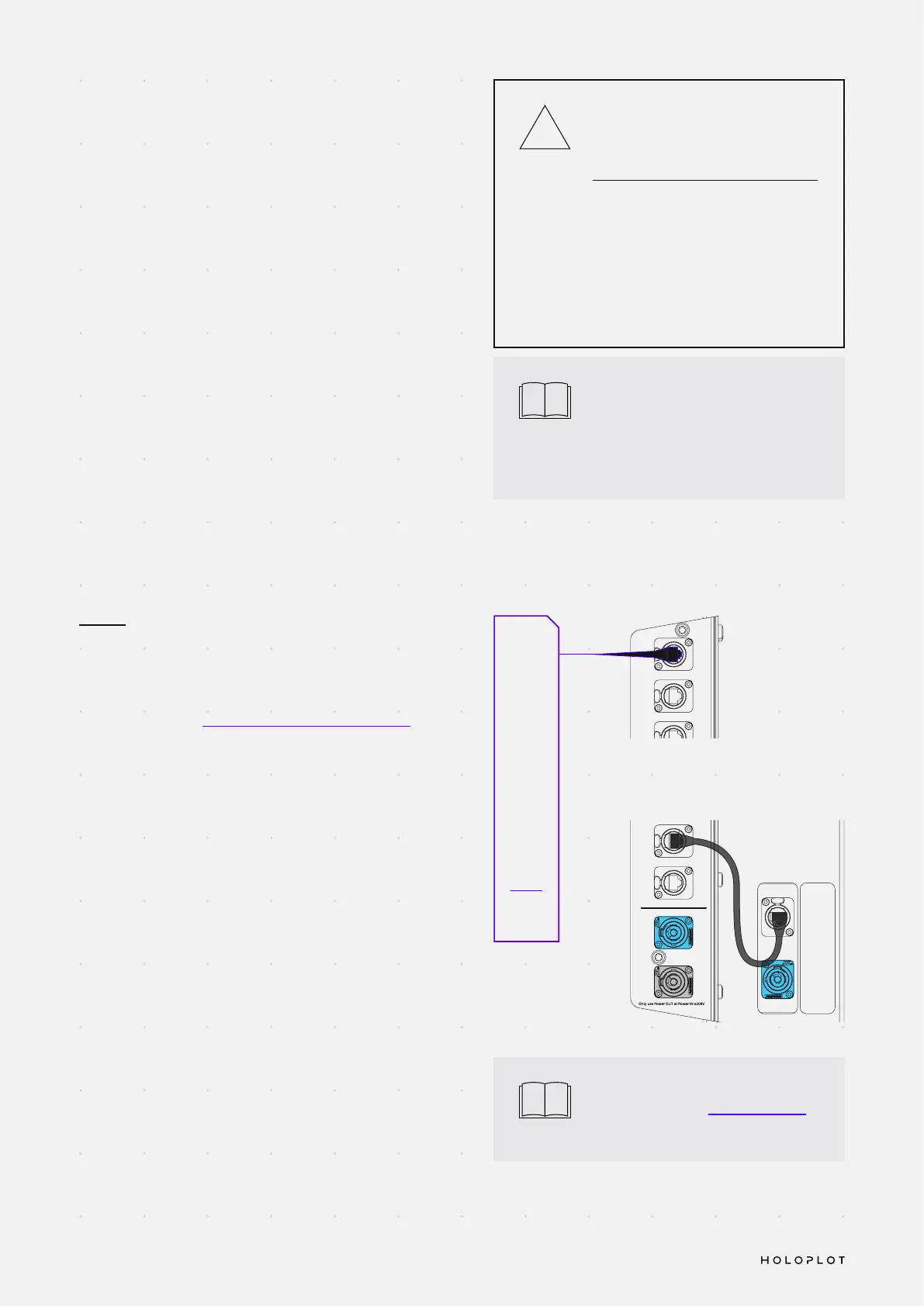
In order to operate the Modul 80-S, the system must be
set up following the Network Setup and Requirements.
The Audio Module needs to be connected to the network
using its “Primary Uplink” connection. This enables
connections to both Control and Dante Audio Network over
a single network cable. To achieve full redundancy, connect
a secondary network switch to its “Secondary Uplink”.
i
The “Status” LED on the Display
Panel will indicate if an error is
detected in the MD80-S by turning
red. The error description appears
on the Display.
i
For more information on redundancy
please refer to the Network Design
section.
K
R
O
W
T
E
N
Secondary
Uplink
Secondary
Downlink
Primary
Downlink
Primary
Uplink
K
N
I
L
O
L
O
H
A
B
1
2
K
N
I
L
B
U
S
N
I
Do not connect
under load
T
U
O
AC Output:
240V
~
9.5A
208V
~
9A
AC Input Range:
115-240V
50-60Hz
AC Input:
115V
~
6.5A
240V
~
12.8A
AC Input Range:
115–240 V
50–60 Hz
AC Input:
115 V
~
1.1 A
240 V
~
0.9 A
Do not connect
under load
Only power from
Electronics Package
at Power
IN ≥ 208 V
SUBLINK
IN
K
R
O
W
T
E
N
Secondary
Uplink
Secondary
Downlink
Primary
Downlink
Primary
Uplink
K
N
I
L
O
L
O
H
A
B
1
2
K
N
I
L
B
U
S
N
I
Do not connect
under load
T
U
O
AC Output:
240V
~
9.5A
208V
~
9A
AC Input Range:
115-240V
50-60Hz
AC Input:
115V
~
6.5A
240V
~
12.8A
AC Input Range:
115–240 V
50–60 Hz
AC Input:
115 V
~
1.1 A
240 V
~
0.9 A
Do not connect
under load
Only power from
Electronics Package
at Power
IN ≥ 208 V
SUBLINK
IN
Network
Primary
Switch with
DHCP
Server
Operating the X1 Modul 80-S
Only switch on the main power
source once all physical power
connections are made.
If the “POWER” LED does not turn
green, switch off the AC power source
immediately and verify that the
voltage is within the required range.
If the problem persists, contact
HOLOPLOT Customer Support.
!
 Loading...