ASSEMBLY STEPS
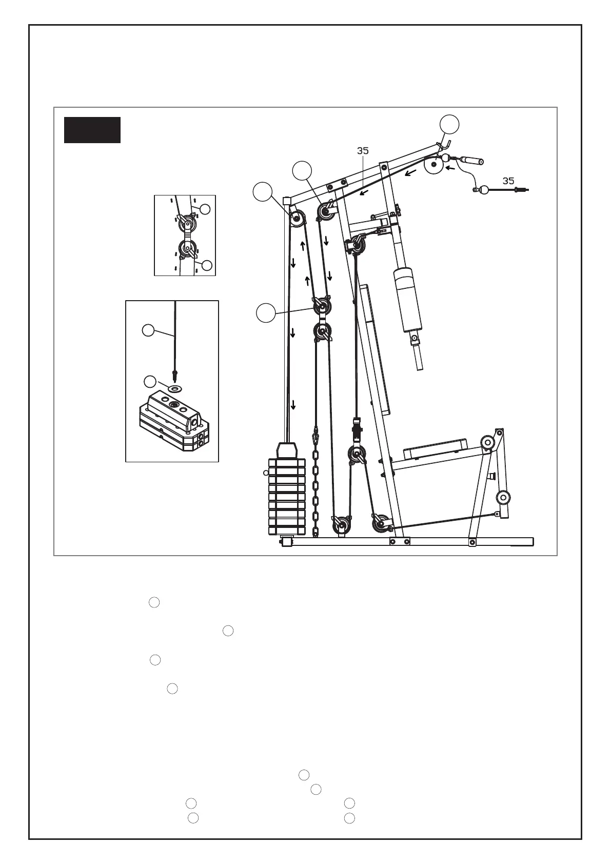
STEP 8: CABLE 35
Installing the pulley system:
1. Install Pulley (32) A onto the Upper Cross Beam (9) using 1 Hex Bolt (60), 2 Washers (67) and 1 Nylon
Nut (70).
2. Once complete, install Pulley (32) B and 2 Pulley Hooks (55) (which are used to help thread the cable)
onto the Support Frame (8) using 1 Hex Bolt (59), 2 Washers (67) and 1 Nylon Nut (70).
3. Install Pulley (32) C and 2 Pulley Hooks (55) to the Pulley U (22) using 1 Hex Bolt (59), 2 Washers (67)
and 1 Nylon Nut (70).
4. Install Big Pulley (32) D (also indicated by a different colour or additional colour mark on it) and 2 Pulley
Covers (54) onto the Upper Cross Beam (9) using 1 Hex Bolt (59), 2 Washers (67) and 1 Nylon Nut (70).
5. Attach the bolt end of Cable 35 to the Selector Shaft (5) with Plastic Washer (26) by screwing it in.
Attach the ball end of Cable 35 to the Lat Bar (19) using 1 Pothook (29).
Threading the cable through the pulley system:
1. Thread Cable 35 through the groove of Pulley (32) A and then through the Upper Cross Beam (9).
2. Thread Cable 35 through the groove over Pulley (32) B .
3. Directly below Pulley (32) B loop Cable 35 under Pulley (32) C .
4. Directly above Pulley (32) C , loop Cable 35 over Pulley (32) D .
STEP-BY-STEP PROCESS FOR ATTACHING THE PULLEYS & THREADING CABLES
36
35
35
26
B
D
A
C
STEP 8
A
A
B
B
B
C
C
C
D
D
37