ASSEMBLY STEPS
Note: Each Butterfly Arm is Labeled with an “L” for the Left (11) and a “R” for the Right (12).
Left and Right is seen as if you were standing behind the unit looking at it (i.e if facing the unit from the
front the Left will now be on your right and visa versa).
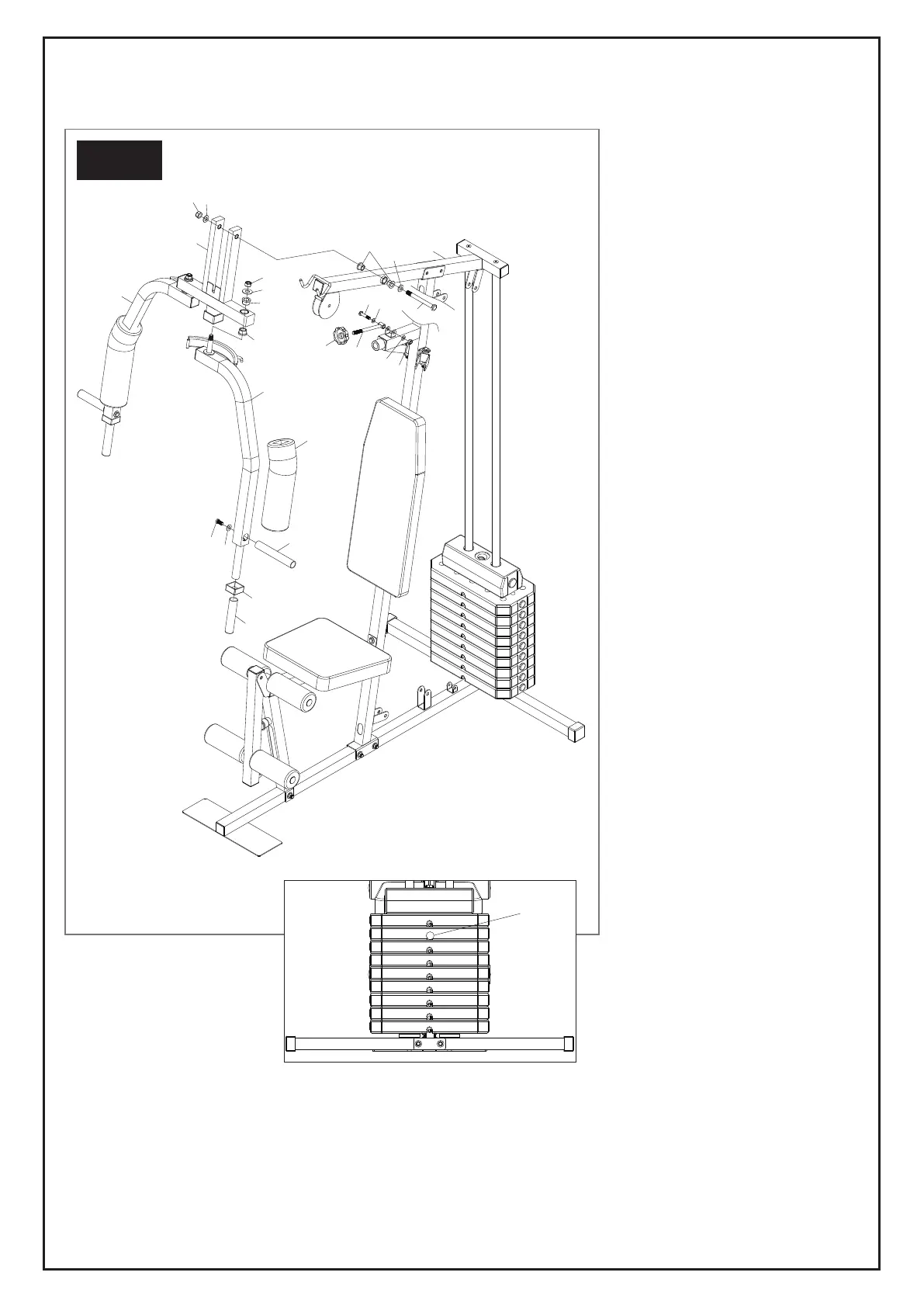
STEP 7:
Attach the Press Bar (10) to the
Upper Cross Beam (9) using 1 Hex
Bolt (56), 2 Washers (66) and 1
Nylon Nut (69).
Please note that 2 Small Oil Bush-
ings (38) have been pre-assembled
onto the Upper Cross Beam (9) as
well as 4 Big Oil Bushings (39) into
the Press Bar (10).
Attach the Right Butterfly Arm (12)
and the Left Butterfly Arm (11) to
the Press Bar (10) using 2 Washers
(66) and 2 Nylon Nuts (69).
Slide the Arm Foam Rollers (31)
onto the Right Butterfly Arm (12) as
well as the Left Butterfly Arm (11).
Attach the Handle Tube (18) to the
Right Butterfly Arm (12) and the Left
Butterfly Arm (11) using 2 Hex Bolts
(61) and 2 Washers (67).
Now slide 2 Middle Empty Plugs
(51) and 2 Handle Grips (46) onto
the Right Butterfly Arm (12) as well
as the Left Butterfly Arm (11).
Attach the Crank (28) to the
Support Frame (8) using 1 Hex Bolt
(63), 2 Washers and 1 Nylon Nut
(71).
Slide Plum Blossom Nut (23) onto
the Crank (28) and secure tightly
once latched onto Press Bar (10).
STEP 7
10
12
11
18
66
56
69
66
39
39
31
46
51
67
61
56
66
9
38
23
63
68
28
68
71
24
36