SPECIFICATION
Engine displacement 30 cc
Maximum engine performance
(in accordance with ISO 8893) 0.78 kW
Maximum rotational frequency
of the the spindle 10,000 min-
1
Engine speed (rotational frequency)
at recommended max. spindle
rotational frequency 12,500 min-
1
Engine speed (rotational frequency)
at idle 2,000-2,500 min-
1
Fuel consumption (in accordance
with ISO 8893) at max.
engine performance 0.52 kg/h
Specific fuel consumption
(in accordance with ISO 8893)
at max. engine performance 0.47 kg/h
Vibration level idling
- Left handle 9.3 m/s
2
- Right handle 12.4 m/s
2
Vibration level racing
- Left handle 7.5 m/s
2
- Right handle 12.5 m/s
2
Sound pressure level
(in accordance with EN ISO 11806:1997,
ISO 7917:1987) 99 dB (A)
Sound power level (in accordance
with ISO 10884) 114 dB (A)
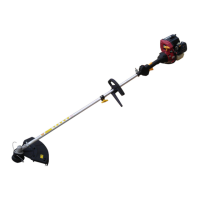
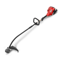
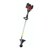
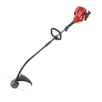
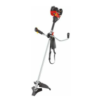
DESCRIPTION
1. Starter grip
2. Strap hanger
3. Left handle
4. Shoulder strap
5. Blade guard
6. Tri-arc blade
7. Gear head
8. Shaft
9. Throttle trigger
10. Trigger handle
11. Ignition switch
12. Throttle interlock
13. Engine housing
14. Grass deflector
15. Line cut-off blade
16. Cutting line
17. Top clamp
18. Handle bar
19. Bottom clamp
20. Handle position adjustment knob
21. Quick release tap
22. Latch
23. "H" high needle
24. Rear housing
25. Torx wrench
26. Screw
27. Muffler guard
28. Bent end of muffler guard
29. Opening in rear housing
30. Mounting bracket
31. Notches
32. Threaded mounting plates
33. Locking tabs
34. Upper flange washer
35. Holding pin
36. String head
37. Spool retainer
38. Drive connector
39. Wrench (16 mm)
40. Cupped washer
41. Blade nut
42. Wrench (13 mm)
43. Dangerous cutting area
44. Direction of rotation
45. Best cutting area
46. Primer bulb
47. Lever
48. Cold start position
49. Warm start position
50. Spool
51. Eyelets
52. Shaft for string head
53. Slots for string head
54. Spring
55. First line
56. Anchor hole
57. Arrows on spool
58. Second line
59. Blade protector
60. Clips
61. "L" Lo needle
62. Filter
63. Slots on air filter base
64. Tabs air filter cover
65. Cover
66. Idle speed screw
ASSEMBLY
HANDLE (Fig. 2)
■ Place the handle bar (18) in the bottom clamp (19)
located on the shaft (8) housing.
NOTE: The throttle trigger (9) must be mounted to the
operator's right side.
17
English
 Loading...