Do you have a question about the Honda 08E61-S84-100 and is the answer not in the manual?
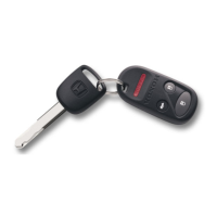
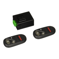
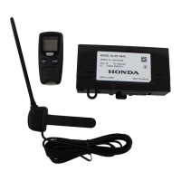
Lists components included in the Keyless Entry Kit.
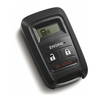
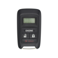
Lists components included in the Attachment Kit.
Lists necessary tools and supplies for installation.
Covers disconnecting battery and removing dashboard lower cover.
Detaches interior light switch trim and harness connector.
Removes fuel lid opener knob and left front trim panel.
Detaches weatherstrip and left kick panel.
Attaches the unit bracket to the control unit with screws.
Wraps cushion tape on antenna and installs relay.
Plugs the 22-pin connector of the keyless entry harness into the control unit.
Attaches keyless entry harness and antenna with wire ties.
Secures unit bracket to the steering hanger beam bracket.
Plugs keyless entry 3-pin connector into vehicle harness.
Routes 6-pin connectors to switch trim opening.
Plugs keyless entry 10-pin connectors into fuse box.
Connects gray 2-pin and brown 2-pin connectors below fuse box.
Attaches fuse labels and connects ground terminal to hood opener lever.
Plugs 4-pin and 1-pin connectors into fuse box.
Cleans instrument panel bracket and applies cushion tape.
Secures keyless entry harness to vehicle harness with wire ties.
Checks wiring, reconnects battery, reinstalls parts.
Includes radio code entry, clock setting, and window auto function reset.
Details steps for PCM idle learn procedure after installation.
This document describes the installation and features of a Keyless Entry System designed for the Honda Pilot, identified by part number 08E61-S84-100 for the kit and 08E65-S9V-100 for the attachment kit. The installation instructions are intended for skilled technicians with proper tools, equipment, and training, and should not be attempted by "do-it-yourselfers."
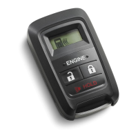
The Keyless Entry System provides remote control functionality for vehicle access, allowing users to lock and unlock the vehicle without using a physical key. It integrates with the vehicle's existing electrical system, including the interior light switch, fuse box, and various connectors, to enable remote operation. The system includes a control unit, a dedicated wiring harness, and two remote controls for user interaction. It also incorporates a relay for proper electrical operation and a unit bracket for secure mounting within the vehicle's dashboard area.
| Brand | Honda |
|---|---|
| Model | 08E61-S84-100 |
| Category | Remote Starter |
| Language | English |