Do you have a question about the Honda 1986 GoldWing GL1200A and is the answer not in the manual?
| Brand | Honda |
|---|---|
| Model | 1986 GoldWing GL1200A |
| Category | Motorcycle |
| Language | English |
Guidelines and warnings for safe servicing procedures, emphasizing hazard identification and precautions.
General disclaimer regarding safety principles and procedures, advising user discretion.
Fundamental rules for servicing, covering parts, tools, and assembly procedures.
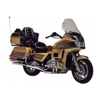
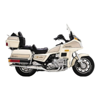
Details and illustration for identifying the specific motorcycle model.
Explanation of the motorcycle's emission control systems, including secondary air and crankcase systems.
Description of the evaporative emission control system specific to California models.
Information on noise emission standards and prohibited tampering acts.
Conversion factors for various units like torque, length, pressure, and temperature.
Detailed general specifications including dimensions, frame, engine, and clutch data.
Specifications related to the Computerized Fuel Injection system components.
Specifications for the motorcycle's electrical system components like lights and charging.
Service limits for various engine and chassis components like cylinder head, crankshaft, and brakes.
Comprehensive list of torque specifications for engine, frame, and other components.
Scheduled maintenance intervals for various items based on mileage or time.
Step-by-step instructions for replacing the fuel filter.
Procedure for removing, cleaning, and installing the air cleaner element.
Instructions for synchronizing the throttle valves for optimal engine performance.
Procedure for removing and replacing the cruise valve element.
Detailed steps for safely removing the engine from the motorcycle frame.
Step-by-step guide for installing the engine back into the motorcycle frame.
Procedure for removing and installing the motorcycle handlebars.
Diagram illustrating the components of the front fork assembly.
Diagram showing the components of the rear shock absorber assembly.
Procedure for removing, disassembling, and installing the front brake master cylinder.
Overview of the ignition system, including ECU control and sensor inputs.
Diagnostic flowcharts for troubleshooting ignition system issues like no spark.
Procedure for inspecting and adjusting the engine ignition timing.
Instructions for removing, installing, and inspecting the ignition coils.
Procedure for inspecting the spark units, including voltage and continuity checks.
Instructions for checking the resistance of the spark unit resistor.
General information and reference to base manual for lights, switches, and instruments.
Diagnostic procedures for issues with displays, lights, and instrument functions.
Wiring diagram and troubleshooting for turn signal and cornering lights.
Inspection procedure for the front brake light switch.
Instructions for installing the oil pressure warning switch.
Procedure for removing, installing, and inspecting the oil pressure sensor.
Procedure for inspecting the main relay for proper operation.
Inspection procedures for turn signal and starter switches on the handlebars.
Step-by-step instructions for removing the fairing lower covers.
General service information for the Computerized Fuel Injection system.
Diagram illustrating the electrical connections of the CFI system components.
Chart correlating symptoms with probable causes and page references for CFI system issues.
Information on the CFI system's self-diagnostic capabilities using LED indicators.
Diagnostic flowcharts for various CFI system problems like no fuel system indicator light.
Procedure for checking fuel pressure and specifications for the CFI system.
Instructions for inspecting fuel injectors, including operation and LED checks.
Procedures for inspecting PB sensors, including LED, voltage, and vacuum tests.
Service procedures for the throttle sensor, including inspection and resistance checks.
Procedures for inspecting the crankshaft angle sensor, including LED, coil, and air gap checks.
Service procedures for camshaft angle sensors, including LED, coil, and air gap checks.
Procedures for inspecting the air temperature sensor, including LED and resistance checks.
Service procedures for the coolant temperature sensor, including voltage and resistance checks.
Inspection and service procedures for the fuel pump and its related relays.
Procedure for removing and installing the CFI Electronic Control Unit (ECU).
Inspection and service procedures for the air valve.
Procedures for removing, disassembling, and assembling the air chamber.
General service information for the Electronic Travel Computer system.
Wiring diagram illustrating the connections for the Electronic Travel Computer.
Diagnostic procedures for issues with ETC displays, indicators, and functions.
Troubleshooting steps for when the clock time cannot be adjusted.
Diagnostic steps for when average speed and trip functions are not working.
Troubleshooting for when the fuel level is not indicated correctly on the display.
Explanation of abnormal indications like flashing bars on the ETC display.
Troubleshooting for incorrect fuel consumption display, both low and excessive.
Diagnostic steps for when the LCD night light fails to illuminate.
Instructions for removing the Electronic Travel Computer unit from the motorcycle.
Steps for disassembling the Electronic Travel Computer unit.
Instructions for assembling the Electronic Travel Computer unit after service.
General service information and precautions for the auto leveling rear suspension system.
Wiring diagram for the auto leveling rear suspension system.
Diagnostic flowcharts for common issues with the auto leveling system.
Troubleshooting steps for when the system displays 'E' indicating no operation.
Diagnostic procedures for when the system displays 'EEE' indicating no operation.
Troubleshooting steps when the LCD display on the auto leveling system is blank.
Troubleshooting for abnormal increase operations in the auto leveling system.
Diagnostic steps when the pump runs but pressure does not increase.
Procedure for checking front and rear air pressure equalization.
Troubleshooting for pressure not decreasing as expected in the auto leveling system.
Troubleshooting for when LCD shows decrease but system does not respond.
Diagnostic steps for rapid pressure loss after a pressure check.
Troubleshooting steps for oil leaks from the air relief hose during decrease.
Procedure for inspecting the air pump relay for continuity and voltage.
Inspection of suspension control switches for continuity and proper operation.
Procedures for removing, disassembling, and assembling the air distributor.
Removal, inspection, and installation of the pressure relief valve.
Procedure for removing and installing the suspension computer.
Procedures for removing, inspecting, and adjusting the height sensor.
General service information and precautions for the cruise control system.
Wiring diagram for the cruise control system.
Diagnostic flowcharts for troubleshooting cruise control system malfunctions.
Troubleshooting steps for when cruise control fails to resume after cancellation.
Troubleshooting steps for excessive cruise speed fluctuation after setting.
Diagnostic procedures for when cruise control cannot be cancelled.
Procedure for inspecting the cruise valve relay for continuity and voltage.
Inspection procedures for the cruise control actuator, including vacuum tests.
Procedure for inspecting vacuum hoses for damage or leaks related to cruise control.
Inspection procedure for the one-way valve in the cruise control system.
Procedure for inspecting the cruise control valve, including vacuum and voltage tests.
Inspection and adjustment procedures for front brake, clutch, and rear brake cancel switches.
Inspection procedures for cruise and set switches, including voltage and continuity checks.
Procedures for removing, disassembling, and assembling the cruise control junction box.
Procedure for checking smooth throttle grip operation and free play.
Instructions for adjusting the throttle cables for proper cruise control function.