CRANKSHAFT
jTRANSMISSION
SERVICE INFORMATION
GENERAL
• The crankcase halves
must
be separated
to
service
the
crankshaft,
connecting
rod
and
transmission
(including
the
shift
fork
and
shift
drum).
To
service
there
parts,
the
engine
must
be
removed
from
the
engine
(Section 7).
• The
following
parts
must
be
removed
before
separating
the
crankcase:
- Oil
filter
(Section 3)
-
Water
pump
(Section
6)
-
Cylinder
head (Section 10)
- Cylinder,
piston
(Section 11)
- Clutch,
gearshift
linkage
and
primary
drive
gear
(Section
8)
-
Alternator,
flywheel
(Section
9)
- Starter
motor
(Section 18)
- Neutral
switch,
oil
pressure
switch
(Section 19)
•
Be
careful
not
to
damage
the
crankcase
mating
surface.
•
When
disassembling,
mark
and store the disassembled parts to ensure
that
they
are reinstalled in
their
original locations.
• Connecting rod
bearing
inserts
are select
fitted
and are
identified
by
color
code. Select
the
replacement
bearings
using
the
selection tables.
After
installing
new
bearings, recheck
them
with
plastigauge
to
verify
correct
clearance.
• Clean and
apply
sealant
to
the
crankcase
mating
surfaces.
Wipe
off
excess sealant
thoroughly.
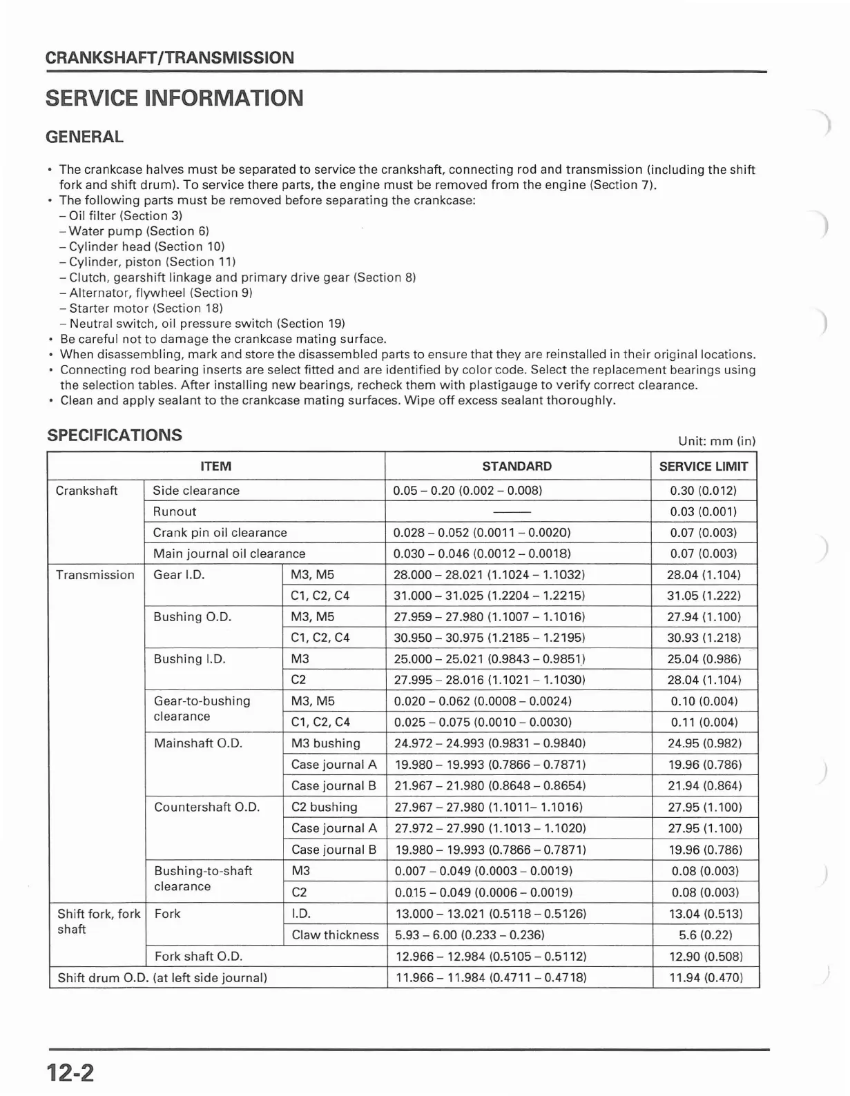
SPECIFICATIONS
Unit:
mm
(in)
ITEM
STANDARD
SERVICE LIMIT
Crankshaft
Side
clearance 0.05 - 0.20 (0.002 - 0.008) 0.30 (0.012)
Runout
--
0.03 (0.001)
Crank pin
oil
clearance 0.028 - 0.052 (0.0011 - 0.0020) 0.07 (0.003)
Main
journal
oil
clearance 0.030 - 0.046 (0.0012 - 0.0018)
0.07 (0.003)
Transmission
Gear I.D. M3,
M5
28.000 - 28.021 (1.1024 - 1.1032) 28.04 (1.104)
C1, C2,
C4
31.000 - 31.025 (1.2204
-1.2215)
31.05 (1.222)
Bushing
a.D.
M3,
M5
27.959 - 27.980 (1.1007 - 1.1016) 27.94 (1.100)
C1,
C2,
C4
30.950 - 30.975 (1.2185 - 1.2195) 30.93 (1.218)
Bushing
I.D.
M3
25.000 - 25.021 (0.9843 - 0.9851) 25.04 (0.986)
C2
27.995 - 28.016 (1.1021 - 1.1030) 28.04 (1.104)
Gear-to-bushing
M3,
M5
0.020 - 0.062 (0.0008 - 0.0024) 0.10 (0.004)
clearance
C1,C2,C4
0.025 - 0.075 (0.0010 - 0.0030) 0.11 (0.004)
Mainshaft
G.D.
M3
bushing
24.972 - 24.993 (0.9831 - 0.9840) 24.95 (0.982)
Case
journal
A 19.980 - 19.993 (0.7866 - 0.7871) 19.96 (0.786)
Case
journal
B
21.967 - 21.980 (0.8648 - 0.8654) 21.94 (0.864)
Countershaft
a.D.
C2
bushing
27.967 - 27.980 (1.1011- 1.1016) 27.95 (1.100)
Case
journal
A 27.972 - 27.990 (1.1013
-1.1020)
27.95 (1.100)
Case
journal
B 19.980 - 19.993 (0.7866 - 0.7871) 19.96 (0.786)
Bushi
ng-to-shaft
M3
0.007 - 0.049 (0.0003 - 0.0019)
0.08 (0.003)
clearance
C2
0.0.15
- 0.049 (0.0006 - 0.0019) 0.08 (0.003)
Shift
fork,
fork
Fork !.D.
13.000 - 13.021 (0.5118 - 0.5126)
13.04 (0.513)
shaft
Claw
thickness
5.93 - 6.00 (0.233 - 0.236) 5.6 (0.22)
Fork
shaft
G.D. 12.966 - 12.984 (0.5105 - 0.5112)
12.90 (0.508)
Shift
drum
a.D.
(at
left
side
journal)
11.966-11.984
(0.4711-0.4718)
11.94 (0.470)
12-2
 Loading...