b.
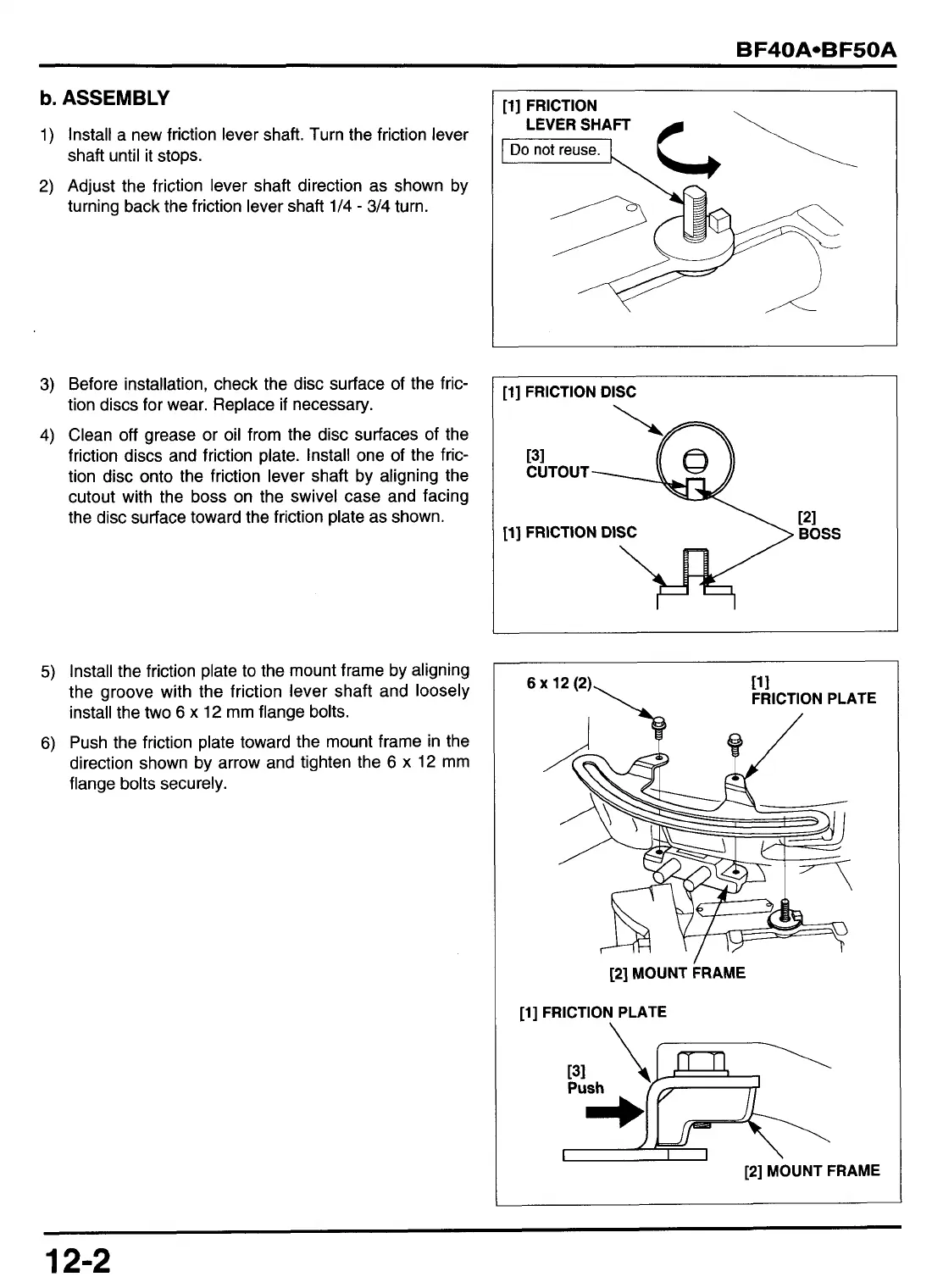
ASSEMBLY
1)
Install a new friction lever shaft. Turn the friction lever
shaft until it stops.
2)
Adjust the friction lever shaft direction as shown by
turning back the friction lever shaft /4
-
314 turn.
3) Before installation, check the disc surface of the fric-
tion discs for wear. Replace
if
necessary.
4) Clean
off
grease or oil from the disc surfaces of the
friction discs and friction plate. Install one of the fric-
tion disc onto the friction lever shaft by aligning the
cutout with the boss on the swivel case and facing
the disc surface toward the friction plate as shown.
5)
Install the friction plate
to
the mount frame by aligning
the groove with the friction lever shaft and loosely
install the two
6
x
12
mm flange bolts.
6)
Push the friction plate toward the mount frame in the
direction shown by arrow and tighten the
6
x
12
mm
flange
bolts
securely.
[l]
FRICTION
p%EyG\
[l]
FRICTION DISC
131
CUTOUT
11
1
\
FRICTION PLATE
6
x
12 (2)
121
MOUNT
FRAME
[l] FRICTION PLATE
\
i
\
I
I
I
\
[2]
MOUNT FRAME
12-2