EasyManua.ls Logo

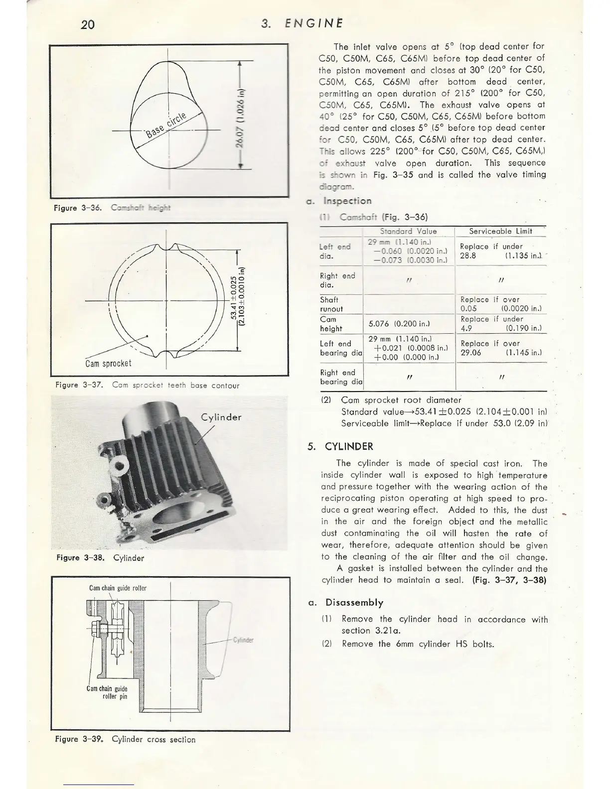
Honda C50 - Cylinder Disassembly; Camshaft Inspection; Cam Sprocket Teeth Base Contour; Cylinder Cross Section

Honda C50
127 pages
Print Icon
To Next Page IconTo Next Page
To Previous Page IconTo Previous Page
Loading...
20
Figure
3-36.
Cc-
~
·::"·
·
e·,;-:
Cam
sprocke
t
Figure 3-
37
. C
om
sp
ro
cket tee h bose
conto
ur
Figure 3-
38.
Cy
li
nder
Cam
chai
n
guide
roll
er
Cam
chain
guide
roll
er
pi
n
Figure 3-
39
.
Cyl
inder cross
sectio
n
3.
ENG
IN~
a.
The inlet
valve
ope
ns
at
5°
(top
dead
center
f
or
C50,
C50M
,
C65,
C65
Ml
before
top
dead
center
of
the piston movement and closes
at
30
°
120
°
for
C50,
C50M
,
C65,
C65M
l
after
botto
m
dead
center,
per
mitting an
open
duration
of
2 15°
(200°
for
C50
,
C50M,
C65,
C65Ml.
The exhaust valve opens
at
40°
1
25°
for
C50
,
C50M
,
C65
,
C65Ml
before
bottom
de
ad
center a
nd
closes
5°
,!5°
before
top
dead
cent
er
'or
C50,
C50M
,
C65,
C65Ml
after
top
dead
center.
- his a
llo
ws
225°
1200°
-"
for
C50
,
C50M
,
C65
,
C65M,l
~
'
exhaust valve
ope
n
duration
. This sequence
3-
35
and
is
called
the
valve timing
spec
io n
R'
ht
lg
en
d
die.
Shaft
run
out
Cam
height
L
eft
end
bearing
die
Right end
bearing
die
(Fig. 3- 36)
:ond
ord
Value
29c;m
1
1.140in
.l
- 0.
060
10.
00
20
in.)
- 0.
073
10.
0030
in
.)
II
5.
076
10.2
00
in.)
29
mm 1
1.1
40
in
.l
+0.02
1
10.0008
in.)
+o
.
oo
10
.000
in
.>
II
I
Serv
iceab
le
lim
it
·
Rep
lace if under
28
.8 I 1.135 in.t •
II
Replace
if
over
0.
05
10.0020 i
n.)
Replace
if
under
4.9
10.190 in.l
Replace if
over
29.06
11.145
in
.)
"
121
Cam sprocket
root
diam
eter
Stand
ard
value
->
53
.
41
±0
.02
5
12
.104±0
.001 i
n)
Se
r
viceab
le limit
->
Replace
if
und
er
53.0
12
.09 in)
5.
CYLINDER
The cylind
er
is made
of
special cast ir
on
. The
inside
cy
linder
wa
ll
is
exposed
to
high ' t
em
p
era
tu
re
and pressure t
oge
ther w ith the
wearing
action
of
the
reciprocating
pist
on
ope
ra
ting
at
high speed to pr
o-
.
duce a
grea
t
wear
i
ng
effect.
Add
ed
to
thi
s,
the dust
in t
he
air and
the
fo
reign
object
and the metallic
dust
co
ntaminating
the
oil will hasten the
rat
e
of
wear,
the
refor
e,
adequate
a
tt
entio n should be given
to
the cleaning
of
the
air
filter
and
the
oil
change.
A gasket
is
installed
be
t
ween
the cyli
nder
and the
cylinder head
to
maintain a seal. (Fig. 3-
37,
3- 38)
a.
Disassembly
(1 l
Re
m
ove
the
cy
lind
er
h
ead
in
accordance
with
sec
tion
3.21 a.
121 Remove the
6mm
cylinder HS
bolt
s.

Table of Contents