54
IV.
FRAME
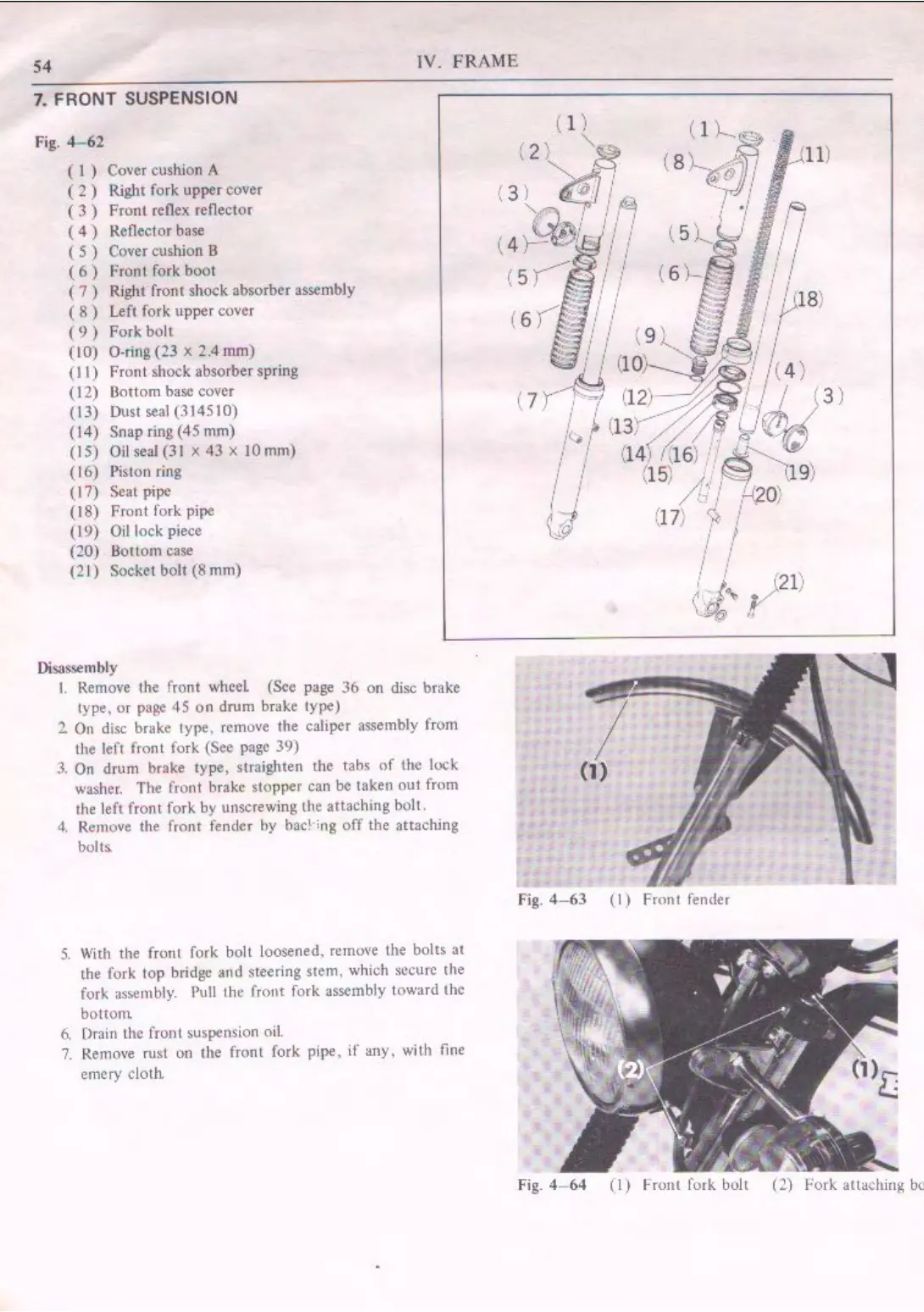
7. FRONT SUSPENSION
Fig.
4-62
( 1 ) Cover cushion A
( 2 ) Right fork upper cover
(
3)
Front
reflex reflector
(
4)
Reflector base
( 5 ) Cover cushion B
(
6)
!'root
fork
boo
t
(
7)
Right front
shock
absorber
assembly
( 8 ) Left fork
upper
cover
(
9)
Fork
bolt
(10) O-ring (23 x 2.4 mm)
(11)
Front
shock
absorber spring
( 12)
Bottom
ha:.: cover
(13) Dust seal (314510)
(14)
Snap
ring (45
mm)
(IS)
Oil
seal (31 x
43
X
IO
mm)
( 16) Piston ring
(17) Seal pipe
( 18)
Front
fork pipe
(I 9) Oil lock piece
(20)
Bottom
case
(2 1) Socket
bolt
(8
mm)
Disassembly
I.
Remove
the
front
wheel
(See page
36
on
disc brake
type,
or
page
45
on
drum
brake
type)
2 On disc brake type, remove
the
caliper assembly
from
the left front fork (See page 39)
3.
On
drum
brake
type,
straighten
the
tabs
of
the
lock
washer.
The
front brake
stopper
can be taken
out
from
the
left
from
fork by unscrewing the
attaching
bolt.
4,
Re111ove
the front fender
by
bad
·ing
off
the attaching
bolts
5.
With
the
front fork boll loosened. remove the
bolts
at
the fork
top
bridge
and
steering stem, which secure
the
fork assernbl)'. Pull the froJlt fork assembly toward
the
bottom
Ii,
Drain
the front
suspension
oil.
7. Remove rust on
the
front fork pipe.
if
any,
with
fine
emery cloth.
Fig,
4-63
(I)
Front
fender
Fig.
4- 64
(I)
Front
fork bolt
(2)
Fork
attaching be
 Loading...