641
Continued
Fuses
Fuse Locations
If any electrical devices are not working,
turn the ignition switch to LOCK (0
*1
and
check to see if any applicable fuse is blown.
Fuse locations are shown on the fuse box
cover. Locate the fuse in question by the
fuse number and box cover number.
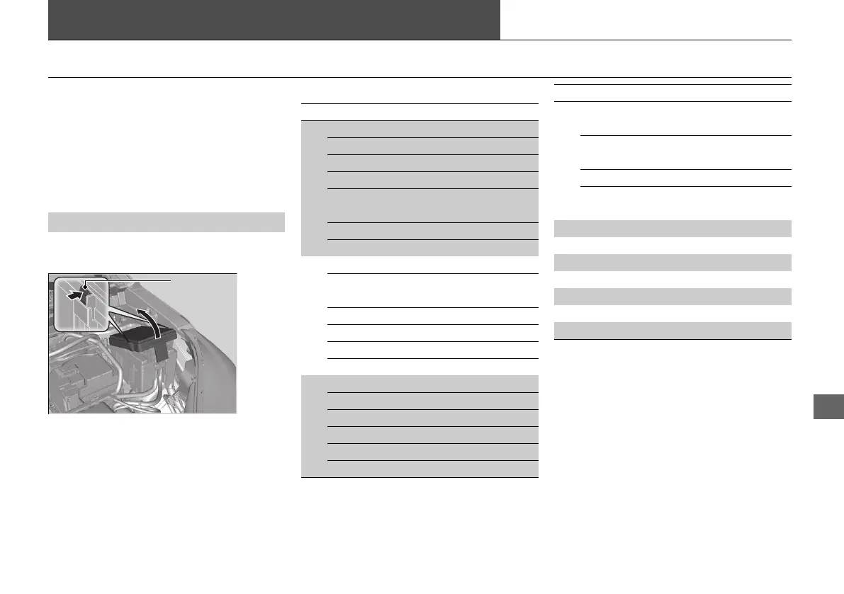
Located near the brake fluid reservoir. Push
the tabs to open the box.
■
Engine Compartment Fuse Box
■
Circuit protected and fuse rating
Circuit Protected Amps
1
VST 1 (30 A)
Electric Brake Booster 40 A
Main Fan Motor 30 A
Relay Module 1 30 A
IG Main 2
*2
30 A
−
*3
−
Relay Module 2 30 A
Battery 125 A
2
EPS 70 A
IG Main 1
30 A
*2
50 A
*3
Fuse Box Option 40 A
Fuse Box 1 60 A
Front Wiper Motor 30 A
Sub Fan Motor 30 A
3
Rear Defroster 40 A
Starter Motor 30 A
Fuse Box 2 40 A
ABS/VSA Motor 40 A
ABS/VSA FSR 40 A
Blower Motor 40 A
*1:Models with the smart entry system have
an ENGINE START/STOP button
instead of an ignition switch.
*2:Models with smart entry system
*3:Models without smart entry system
4
Option Block 1
*2
(40 A)
−
*3
−
Option Block 2
*2
(40 A)
−
*3
−
VST 2 (30 A)
Power Tail Gate
*2
(40 A)
−
*3
−
5 VB ACT 7.5 A
6 Washer 15 A
7 FI Main 15 A
8 FI Sub 15 A
9 Stop Lights 10 A
10 Injector 20 A
11 LAF 7.5 A
Circuit Protected Amps
21 CR-V PET ELP_MAP_HMIN_HCM-31TLA6400.book 641 ページ 2020年9月2日 水曜日 午後1時35分