FUEL SYSTEM (PGM-FI)
6-36
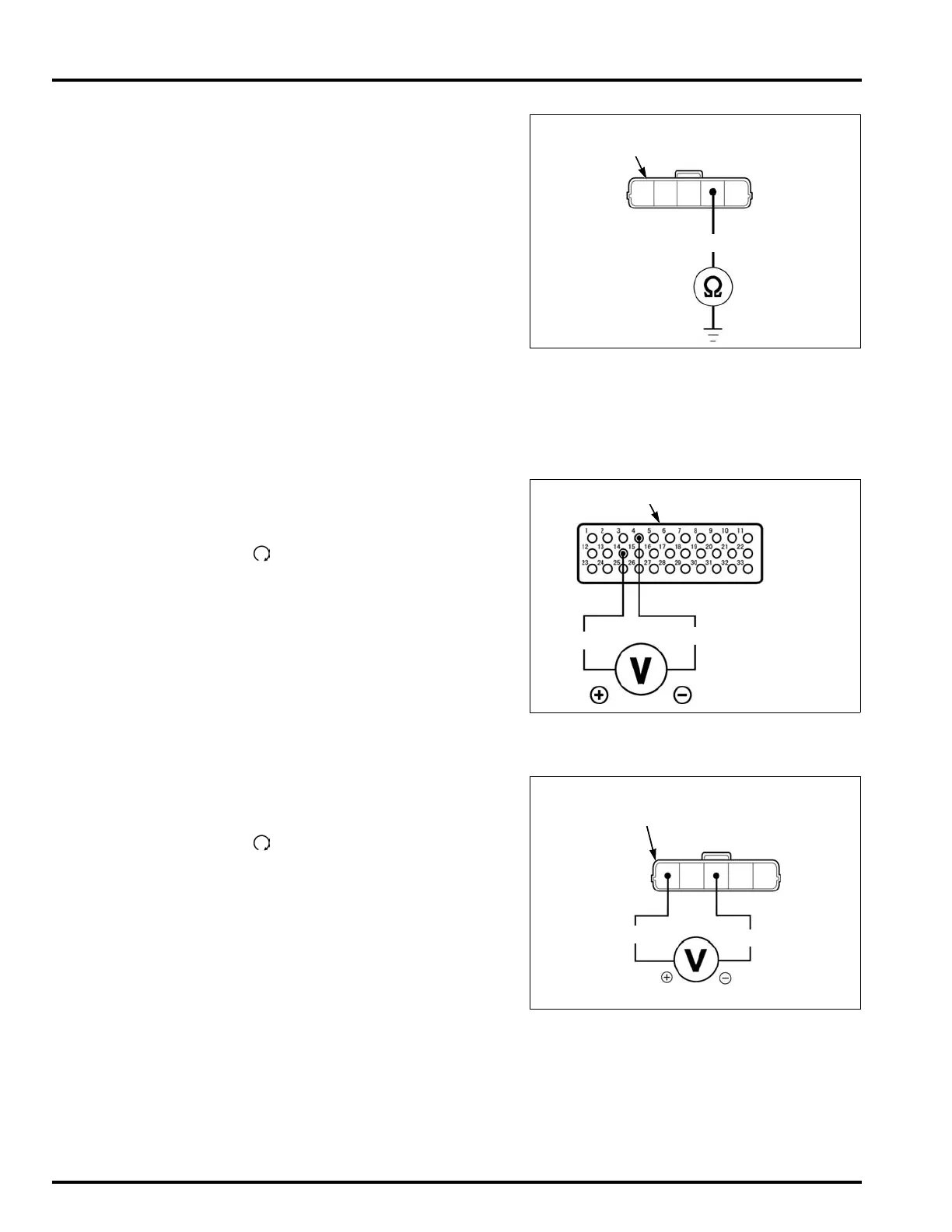
5. TP Sensor Output Line Short Circuit Inspection
Turn the ignition switch OFF.
Disconnect the test harness and ECM 33P con-
nector disconnected.
Check for continuity between the sensor unit 5P
(Black) connector terminal of the wire harness
side and ground.
Is there continuity?
YES – Short circuit in White/Red wire
NO – Replace the sensor unit with a new one,
and recheck (Faulty TP sensor)
MIL 9 BLINKS (IAT SENSOR)
• Before starting the inspection, check for loose or
poor contact on the sensor unit 5P (Black) con-
nector and recheck the MIL blinking.
1. IAT Sensor system Inspection
Turn the ignition switch OFF.
Connect the ECM test harness to ECM connector
(page 6-14).
Turn the ignition switch ON and engine stop
switch " ".
Measure the voltage at the test harness termi-
nals.
Is the voltage within 2.7 – 3.1 V?
YES – • Intermittent failure
• Loose or poor contact on the ECM
connector
NO – GO TO STEP 2.
2. IAT Sensor Output Voltage Inspection
Turn the ignition switch "OFF".
Disconnect the sensor unit 5P (Black) connector.
Turn the ignition switch "ON" and engine stop
switch " ".
Measure the voltage at the sensor unit 5P (Black)
connector of the wire harness side.
Is the voltage within 4.75 – 5.25 V?
YES – GO TO STEP 3.
NO – GO TO STEP 4.
Connection: White/Red (+) – Ground (–)
5P (Black) CONNECTOR
(Wire side of female terminal)
W/R
Connection: A14 (+) – A4 (–)
Standard: 2.7 – 3.1 V (20°C/68°F)
TEST HARNESS PIN BOX
W/Bu
G/O
CONNECTION:
White/Blue (+) – Green/Orange (–)
STANDARD: 4.75 – 5.25 V
5P (Black) CONNECTOR
(Wire side of female terminal)
W/Bu
G/O
 Loading...