English: Page 1 • Français : Page 6 • Español: Página 11
3 69-2251EFS—03
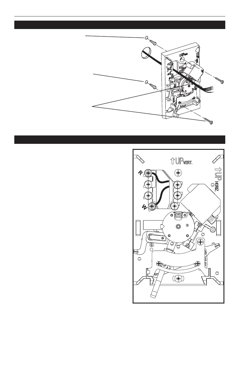
1. Pull wires through wire hole.
Position base on wall, level
and mark hole positions.
2.
Drill holes (3/16” holes for
dr
ywall, 7/32” holes for plas-
ter), then tap in supplied wall
anchors.
3.
P
ull wires through base, posi-
tion over anchors, and insert
screws. Check level if desired,
then tighten screws.
Base installation
1. Loosen screw terminals, insert bare wires
beneath screws, then re-tighten screws.
2. Push any excess wire back into the wall
opening
3. Plug the wall opening with nonflammable
insulation to prevent drafts from affecting
thermostat operation.
Terminal Designations
R R power. Connect to 24 V hot on secondary
side of heating/cooling transformer or R on
furnace/boiler for 750 mV systems.
W
1
Heat relay.
Y
2
Cool relay, or
normally open hot water valve.
G Fan relay (select models only)
1
T822K and T827K
2
T822L
Wire specifications
Use 18-gauge thermostat wire. Shielded
cable is not required.
Wiring
 Loading...