Mounting and Connection Instructions - Door module RS485 23
10. Connections
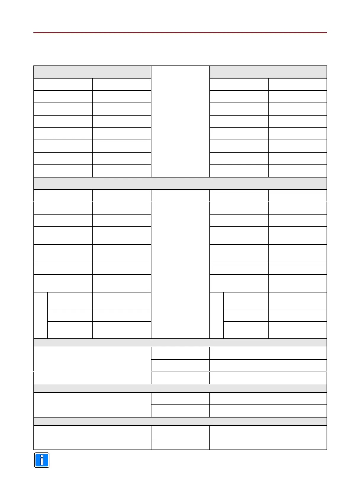
Terminal assignment to fill in the lines and colors of the cables.
Reader 1 Reader 2
Shield Shield
12V DC
(max. 100mA) 12V DC (max. 100mA)
0V 0V
Clock / D0* Clock / D0*
Data / D1* Data / D1*
LED red LED red
LED yellow LED yellow
LED green LED green
* D0 / D1 only Wiegand reader
OUT 3 EN - RS-485
Power supply (S)
power supply (mains)
0V 0V
Input 2
(Door strike key)
Input 1
(Door strike key)
Input 3
(12k1 end-of-line resistor)
Input 4
(12k1 end-of-line resistor)
0V 0V
Input 5
(12k1 end-of-line resistor)
Input 6
(12k1 end-of-line resistor)
Relay 1
normally closed
contact
Relay 2
normally closed
contact
common contact common contact
normally open
contact
normally open
contact
Connection terminal RS-485 D*
D
0V
Power supply 12V DC
0V
Tamper contact TC
0V
Observe current consumption of external devices, see chapter 3.4.
 Loading...