HW-500-003 2 I56-3934-002R
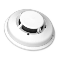
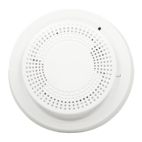
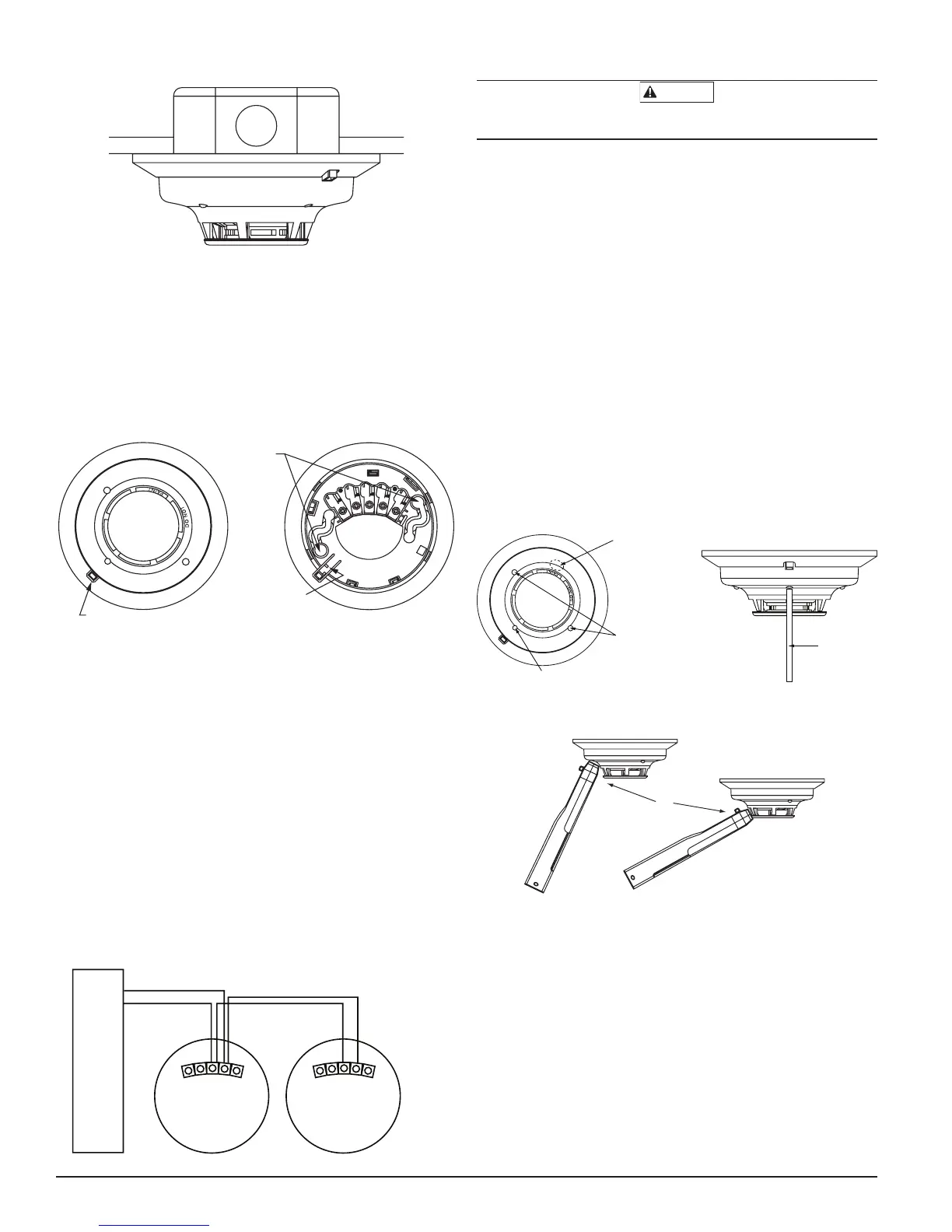
FIGURE 1: MOUNTING OF DETECTOR
S0121-00
TAMPER-RESISTANT FEATURE
The 5193SD/SDT detector includes a tamper-resistant feature that prevents
removal from the mounting base without the use of a tool. To engage the tam-
per-resistant feature, cut the small plastic tab located on the mounting base
(Figure 2), and then install the detector. To remove the detector from the base
once it has been made tamper resistant, use a small screwdriver to depress the
square tamper release tab, located on the skirt of the mounting base, and turn
the detector counterclockwise.
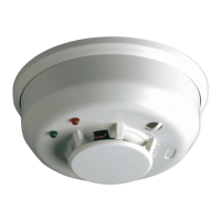
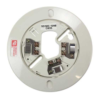
FIGURE 2: TAMPER-RESISTANT FEATURE
SNAP OFF TAB
FOR TAMPER LOCK
TAMPER
RELEASE TAB
DIRECT MOUNT
HOLES
S0226-00
WIRING DIAGRAM
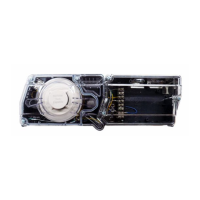
FIGURE 3: WIRING DIAGRAM, 5193SD/SDT
S0133-01
INSTALLATION
Remove power from alarm control unit or initiating device circuits before in-
stalling detectors.
NOTE:
To install units so that corresponding LEDs are lined up, refer to the
“Green LED” indicator on the base.
1. Wire the mounting base screw terminals per Figure 3.
2. Place detector on the base and rotate clockwise. The detector will drop
into the base and lock into place with a “click”.
3. After all detectors have been installed, apply power to the alarm control
unit or initiating device circuits.
4. Test each detector as described in
Testing.
5. Reset all the detectors at the system control panel.
6. Notify the proper authorities that the system is in operation.
TESTING
Detectors must be tested after installation and following maintenance.
NOTE:
Before testing, notify the proper authorities that maintenance is being
performed and the system will be temporarily out of service. Disable the zone
or system undergoing maintenance to prevent any unwanted alarms.
Ensure proper wiring and power is applied.
After power up, allow 50
seconds for the detector to stabilize before testing.
TEST 5193SD/SDT DETECTOR AS FOLLOWS:
A.Test Switch
S0135-01
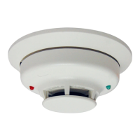
FIGURE 4: RECESSED TEST SWITCH OPENING AND SENS-RDR POSITION
PUSH RECESSED
SWITCH WITH A
0.18w MAX.
DIAMETER TOOL
LED
RECESSED TEST SWITCH
POSITION SENS-RDR
AT AN ANGLE ON THE
OVAL AREA OR AT THE
CHAMBER OPENING
BY THE WORD “PAINT”
FIGURE 5: POSITION OF READER
S0227-00
1. An opening for the recessed test switch is located on the detector hous-
ing (See Figure 4).
2. Insert a small screwdriver or allen wrench (0.18˝ max.) into the test
switch opening; push and hold.
3. If the detector is within the listed sensitivity limits, the detector’s red
LED should light within five seconds. An alarm should be annunciated at
the system’s control or console within 5 seconds.
B. Smoke Entry Test
Canned aerosol simulated smoke (canned smoke agent) may be used for
smoke entry testing of the smoke detector. Tested and approved aerosol
smoke products are the Smoke Detector Tester model 25S available from
Home Safeguard Industries and Chekkit Smoke Detector Tester mod-
els CHEK02 and CHEK06 available from SDi. When used properly, the
canned smoke agent will cause the smoke detector to go into alarm.
WIRING INSTALLATION GUIDELINES
All wiring must be installed in compliance with the National Electrical Code,
applicable state and local codes, and any special requirements of the local
Authority Having Jurisdiction.
Proper wire gauges should be used. The conductors used to connect smoke
detectors to the alarm control panel and accessory devices should be color-
coded to reduce the likelihood of wiring errors. Improper connections can
prevent a system from responding properly in the event of a fire.
The screw terminals in the mounting base will accept 14–22 gauge wire. For
best system performance, all wiring should be installed in separate grounded
conduit; do not mix fire alarm system wiring in the same conduit as any other
electrical wiring. Twisted pair may be used to provide additional protection
against extraneous electrical interference.
Wire connections are made by stripping approximately
1
/4-inch of insulation
from the end of the feed wire, inserting it into the proper base terminal, and
tightening the screw to secure the wire in place.
 Loading...