Do you have a question about the Honeywell 5806W3 and is the answer not in the manual?
Details visual and audible status indications provided by the detector's LEDs and sounder.
Explains how the detector identifies, signals, and manages low battery conditions.
Steps for enrolling the smoke detector's serial number into the control panel system.
Instructions for selecting a location and physically installing the detector base and unit.
Explains methods for testing the smoke detector's functionality using test switches or smoke.
Details how to test the wireless communication path between the detector and the control panel.
Describes testing to ensure all programmed loops transmit correctly to the system.
Lists the technical specifications of the smoke detector, including power, dimensions, and operating conditions.
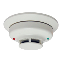
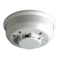
The Honeywell 5806W3 is a photoelectronic smoke detector equipped with a built-in wireless transmitter, designed for use with wireless alarm systems that support 5800 series devices. It is compatible with any 5800 series wireless receiver/transceiver for residential installations, and for commercial applications, requires the 5881ENHC or 5883H receiver. This detector is capable of transmitting alarm, tamper, maintenance, and battery condition messages to the system's receiver. The maintenance signal adheres to NFPA 72, 7-2.2 sensitivity test requirements and is UL approved.
At its core, the 5806W3 utilizes a state-of-the-art optical sensing chamber and an advanced microprocessor. This microprocessor enables the detector to automatically maintain optimal operation at its factory-calibrated detection levels. This is achieved even when sensitivity is affected by contaminants accumulating in the smoke chamber, thanks to a built-in Drift Compensation algorithm. For this feature to function correctly, the chamber must never be opened while the smoke detector is powered, which includes during cleaning, maintenance, or screen replacement.
The detector provides local visual and audible indications of its status through two LEDs (green and red) and a piezoelectric horn. During initial power-up, both LEDs blink synchronously every 5 seconds for approximately 20 seconds. Once the power-up cycle is complete and the detector is operating normally within its listed sensitivity range, the green LED blinks once every 10 seconds. If the detector requires maintenance due to its sensitivity shifting outside the listed limits, the red LED blinks once every 5 seconds. In a smoke alarm condition, the red LED blinks every 1 second, and the piezoelectric horn emits the ANSI S3.41 temporal pattern. If a low battery condition is detected, the red LED blinks every 45 seconds. The LED indications are supplementary and should not replace the specified testing procedures.
The piezoelectric horn generates the ANSI S3.41 temporal pattern during an alarm. When an alarm occurs, a message is sent to the wireless control panel, and the detector's zone number is displayed on the console. Alarm messages are transmitted every 4 seconds until the smoke condition clears and the detector resets. During an alarm, pressing the detector's test switch will silence the horn for 5 minutes. Once the detector resets, a RESTORE message is transmitted to the control panel, allowing the transmitter's zone number to be cleared from the panel. When the detector reaches its compensation limit, it transmits a maintenance signal to the panel.
The 5806W3 is powered by a single 3-volt CR123A or DL123A Lithium battery (included). The detector performs a low battery check at least every 65 minutes. Upon detecting a low battery, the transmitter sends a low battery message to the control panel, which then beeps and displays the detector's zone number. Additionally, the red LED of the 5806W3 will blink every 45 seconds, and the test switch will be disabled. This low battery condition persists for a minimum of 7 days, after which the detector's horn will "chirp" approximately every 45 seconds. Pressing the test switch during this chirping period will silence the chirps for 12 hours. It is recommended to replace the battery before the chirping begins with a fresh one.
Installation of the mounting base is simplified by features compatible with drywall fasteners or other securing methods. For mounting, first determine the optimal location for strong wireless transmission and proper smoke detection. A good transmission path must be established from the proposed mounting location before permanent installation. The detector's serial number must be "enrolled" into the system prior to mounting. The mounting base can be installed on the ceiling or wall (if local ordinances permit) using the provided screws and anchors. The detector is then turned clockwise onto the mounting base until it clicks into place. The detector must not be attached to removable ceiling panels; instead, it should be attached across a panel support.
The smoke detector must be enrolled in the control panel for system operation. The 5806W3 smoke protection zone must be enrolled as Loop 1 with an "Input Type" of 3 (supervised RF). The detector can also monitor Maintenance (transmitted as Loop 2) and Tamper (transmitted as Loop 4). To utilize the Maintenance feature, each loop must be programmed as a separate zone in the 5800 series wireless compatible panel. Loop 1 (Smoke) should be programmed as a Fire zone (type 9 or 16), and Loop 2 (High/Low Maintenance) as a 24-Hr. Trouble zone (type 19). Loop 2 High/Low Maintenance is supported only on commercial control panels like the Vista-128FBP. Input Type 03 (3 on some controls) is used for the supervised RF Transmitter. To transmit the serial number during programming, the tamper switch is activated by rotating the detector counter-clockwise on its base until it snaps open, then returning it to the clockwise position until it snaps into place. The fire protection zone enrolled must always be Loop 1; otherwise, fire annunciations will not be reported by the control.
The detector includes a built-in tamper switch that triggers a CHECK signal at the console if the detector is removed from its mounting base. A tamper-resistant feature prevents removal without a tool. To engage this feature, a small plastic tab on the mounting base (Figure 2) must be cut off before installing the detector. To remove a tamper-resistant detector, a small screwdriver is used to depress the square tamper release tab on the skirt of the mounting base, then the detector is turned counter-clockwise.
Testing the sensor is crucial. Before testing, the central station must be notified that the smoke detector system is undergoing maintenance to prevent unwanted alarms. During initial power-up, SENS-RDR or canned smoke should not be used. These methods can be used after the power-up sequence is complete. Detectors must be tested after installation and following periodic maintenance. Testing methods include:
Signal strength testing should be performed according to NFPA 72 requirements to ensure a strong communication path with the control panel. This involves activating the wireless system's GO/NO GO TEST mode from the keypad, then depressing and holding the smoke detector's TEST switch. If the detector is within proper sensitivity limits and has not detected a low battery, it should immediately transmit an alarm signal. The built-in horn will sound about 2.5 seconds after pressing the button. The wireless system's keypad should emit at least three audible sounds upon receiving the alarm transmission and display the transmitting detector's zone number. Releasing the TEST switch will stop the horn, and the zone number will clear from the console display. If the console does not respond, check battery polarity and freshness. For initial installations, try moving the detector to another location for better reception and ensure the detector has been "enrolled" by the control panel. The system's TEST mode should then be turned off from the keypad.
Programmed loops should be tested before installation to ensure all intended loops are operational. This involves activating the system's TRANSMITTER ID SNIFFER mode from the keypad. All programmed wireless zones will be displayed sequentially on the keypad. After mounting the detector, pressing its TEST switch should cause all zones associated with the smoke detector to disappear from the keypad on the next display cycle, indicating successful transmission from each programmed loop. Once testing is complete, the Installer code + OFF key exits TEST mode. After all system testing, the central station should be notified that the system is back online.
Maintenance procedures require notifying the proper authorities and the central station that maintenance is being performed and the system will be temporarily out of service. The zone or system undergoing maintenance should be disabled to prevent unwanted alarms. The procedure involves:
| Alarm Sound Level | 85 dB |
|---|---|
| Temperature Range | 40°F to 100°F |
| Wireless Compatibility | Yes |
| Operating Voltage | 3V |
| Operating Frequency | 345 MHz |
| Power Source | Battery |
| Compatibility | Honeywell Wireless Systems |
| Range | 200 ft (61 m) open air |