Do you have a question about the Honeywell 6820 and is the answer not in the manual?
Provides a general overview of the 6820 system's features and capabilities.
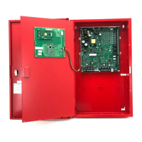
Details the physical components and hardware capabilities of the 6820 panel.
Explains hardware for linking multiple panels for communication and annunciation.
Lists the software capabilities, including zones, output groups, and advanced features.
Highlights specific features of the 6820EVS model, including EVS capabilities.
Defines key terminology used throughout the manual for clarity.
Lists hardware products compatible for use with the control panel.
References other documents for additional detailed information.
Outlines FCC requirements and compliance information for telephone line connections.
Details UL requirements for various installation types and standards compliance.
General UL requirements applicable to all device installations.
Discusses UL 864 certification for fire alarm control equipment.
Specific UL requirements for central station system installations.
UL requirements for local protected fire alarm system installations.
UL requirements for remote station fire alarm system installations.
UL requirements for CO detection system installations per NFPA 720.
Outlines minimum configurations to meet NFPA standards.
Lists the items included in the 6820 shipment for verification.
Details environmental conditions for proper panel installation and operation.
Recommends downloading the latest software versions for optimal product performance.
Lists terminal descriptions and their respective electrical ratings.
Provides steps to determine system current draw and battery needs for installation.
Outlines requirements for using the current draw worksheet for system calculations.
Details current draw for SK SLC devices to aid in battery calculations.
Details current draw for SD SLC devices to aid in battery calculations.
Provides calculations for maximum battery standby load based on standby hours.
Provides instructions for mounting the control panel cabinet, including surface and flush mounting.
Offers precautions to prevent water damage to the control panel cabinet.
Details the procedure for removing the control panel assembly from its housing.
Explains the use of the Ethernet connection for IP communication.
Illustrates the layout of the 6820 control panel board assembly.
Provides guidelines to avoid induced noise and ensure proper wiring.
Details the connection procedure for AC power to the control panel.
Explains battery requirements and connection procedures for system power.
Describes the use and installation of RBB accessory cabinets for backup batteries.
Information on calculating SBUS wire distances and wiring configurations.
Guides users in calculating SBUS wiring distances based on current draw and wire gauge.
Illustrates SBUS Class A and Class B wiring configurations.
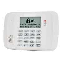
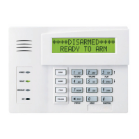
Provides instructions for installing the 6855 remote annunciator.
Details the mounting procedures for the 6855 remote annunciator.
Explains how to connect the 6855 annunciator to the control panel.
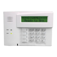
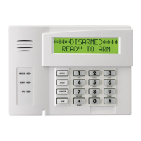
Instructions for installing the 5860 remote annunciator.
Details the mounting procedures for the 5860 remote annunciator.
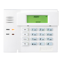
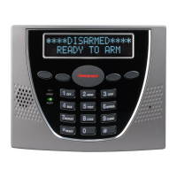
Instructions for installing the 6860 remote annunciator.
Details the mounting procedures for the 6860 remote annunciator.
Explains how to connect the 6860 annunciator to the control panel.
Instructions for installing the 5815XL SLC expander.
Details how to connect the 5815XL to the control panel.
Instructions for installing the 6815 SLC expander.
Details how to connect the 6815 to the control panel.
Instructions for installing the 5824 module for printer connectivity.
Guides users in configuring options for the 5824 module.
Details the installation of the 5880 LED I/O module.
Illustrates the board layout and terminal locations for the 5880 module.
Explains how to connect the 5880 module to the FACP.
Provides instructions for wiring LEDs to the 5880 module.
Details wiring procedures for dry contact inputs on the 5880 module.
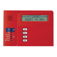
Instructions for installing the 5865-3 and 5865-4 LED annunciators.
Explains how to connect the 5865 annunciator to the FACP.
Details mounting procedures for the 5865 annunciator.
Guides users through configuring SBUS modules for system operation.
Explains how to assign unique IDs to SBUS modules using DIP switches.
Provides instructions for connecting telephone lines to the panel.
Details the functionality and wiring of Flexput I/O circuits.
How to install conventional notification appliances for Class A and B wiring.
How to install conventional initiating devices for Class A and B configurations.
Instructions for connecting 2-wire smoke detectors to the control panel.
Instructions for connecting 4-wire smoke detectors to the control panel.
Explains how to use Flexput circuits for auxiliary power applications.
Details the use and installation of onboard relays for system control.
Describes the dedicated Form C trouble relay and its function.
Explains the installation and configuration of programmable Form C relays.
Covers connecting the panel to remote station receivers.
Instructions for connecting the Keltron Model 3158 for remote station reporting.
Details connecting the panel to a city box using the 5220 module.
Explains using the addressable relay module for city box connections.
Instructions for polarity reversal connections using 5220 and 7644-L8 modules.
Describes connecting a remote station transmitter via dry relay contacts.
Explains features of the 6820 network system for linking panels.
Describes how panels are linked for common communications to a central station.
Details wiring methods like fiber optic and copper wire for panel connectivity.
Explains the use of the SK-NIC for linking 6820 panels.
Covers wiring options for the SK-NIC network interface card.
Details the use of fiber optic modules for SK-NIC communication.
Illustrates wiring configurations for twisted pair and fiber optic connections between panels.
Guides users on setting unique network IDs for each panel using DIP switches.
Tools for diagnosing network performance and status.
Allows pinging panels on the network to check connectivity and response times.
Displays statistics indicating network performance.
Displays statistics indicating voice network performance.
How to program network options using the built-in annunciator or HFSS.
Identifies and manages panels connected to the network as members or guests.
Allows editing panel names and site names within the network.
Explains how to change the Network Panel ID, requiring careful consideration.
Establishes communication between the panel and a computer running HFSS.
Manages user access codes for panel functions and security levels.
Configures reporting events to a central station.
Customizes voice system messages and settings.
Allows adjustment of timers for voice system events and controls.
Enables editing of voice commands for system events and outputs.
Redistributes network programming changes across the network.
Automates many programming tasks, simplifying system setup and device configuration.
Details how JumpStart configures input points, zones, and default mappings.
Explains how JumpStart creates and assigns output groups and circuits.
Step-by-step guide to executing the JumpStart Auto-Programming process.
Provides a high-level overview of mapping inputs to outputs and zones to groups.
Explains how input points are assigned to input zones for system logic.
Details how notification and relay output circuits are assigned to groups.
Describes mapping zone/panel/site events to output groups and patterns.
Shows how LED points are mapped to zones and output groups for status indication.
Instructions for using the HFSS software for control panel programming.
How to program the panel directly using a system annunciator.
Steps for entering and exiting panel programming mode via the annunciator.
A quick reference for panel programming options and their locations.
Details programming requirements specific to UL 864 and UL 2572 standards.
Lists available modules and their programming options.
How to edit module ID, name, and specific features.
Step-by-step process for adding new hardware modules to the system.
Procedure for removing a module from the system configuration.
How to view a list of all installed modules in the system.
Programming options related to defining and configuring zones.
How to edit zone name, properties, and accessory options.
Programming options for organizing output points into groups.
How to edit group names and properties, including voice and non-voice settings.
How to program characteristics of individual input points.
Specific instructions for programming points on the 5815XL module.
Specific instructions for programming points on the 6815 module.
Instructions for programming points on the 5895XL module.
Specific instructions for programming points on 5880/5865 modules.
Instructions for programming points on the 5496 module.
Details programming points for EVS amplifiers.
Instructions for programming points on EVS-VCM and EVS-RVM modules.
Customizes software options affecting general system operation.
Configures communication settings like Auto Test Time, Phone Lines, and Ethernet.
Allows setting system time parameters like Water Flow Delay and Alarm Verify.
Configures options like strobe synchronization and auto display events.
Adjusts system clock for Daylight Saving Time.
Allows customization of the panel's banner message displayed in normal mode.
Configures the panel to accept different SLC device protocols (SD, IDP, SK).
Guides users on running JumpStart to auto-learn system hardware.
Resets the panel to factory default settings, clearing all programming.
Customizes voice system messages and settings.
Used to program custom messages into the Voice Control Module (VCM).
Allows modification of other voice system settings.
Describes the annunciator panel and its components like LEDs and LCD.
Details the control panel's LCD display for system messages and status.
Explains how to navigate the control panel's menu system.
Describes the login process for accessing the panel, including admin and user profiles.
Provides an overview of the main menu options and their functions.
Covers fundamental system operations and user interactions.
How to set the system's current time and date.
Procedures for disabling or enabling individual points or groups of points.
How to access and view the system's event history log.
Steps to initiate and conduct a fire drill test of the system.
How to perform an indicator test to check LEDs, PZT, and LCD functionality.
Procedures for conducting a walk test to verify system operation.
Steps to perform a communicator test for central station reporting.
How to manually register the panel with AlarmNet.
Procedure to silence audible alarms and troubles from the panel.
Steps to reset alarms and troubleshoot conditions within the system.
How to check detector sensitivity compliance with NFPA 72.
How to view the status of individual points within the system.
How to view details of active alarms or troubles on the system.
Accesses information about the panel, firmware, and system version.
Describes how the control panel handles event priorities and system control.
Explains how the panel manages control between fire and emergency systems.
Details how system override disengages output activations for conflicting messages.
Defines priority levels for different event types for controlling output groups.
Describes how the panel behaves in different operating modes like Normal, Alarm, and Trouble.
Explains the functionality of multi-site annunciators and user access.
Covers the panel's support for single and double interlock zone releasing.
Details the conditions required for pre-alert and general alarm outputs in single interlock zones.
Outlines conditions for pre-alert and general alarm outputs in double interlock zones.
Explains the operation cycle of the smoke alarm verification feature.
Describes the use and programming of function keys (F-Keys) for macros and events.
Introduces the EVS system and its integration with the fire alarm panel.
Explains the functions of the Local Operating Console (LOC) for EVS interaction.
Details the functionality of the keys and LEDs on EVS-VCM and EVS-RVM modules.
Governs how EVS Control is obtained, considering priority, lockout, and user access.
How to activate the Emergency System and page using the LOC interface.
Allows users to toggle output areas for microphone paging in Manual EVS State.
Enables selecting EVS messages and toggling output areas for playback.
How to generate an EVS event and speak a custom message using the microphone.
Procedure for passing EVS Control between LOCs with the same priority.
How to exit the LOC EVS interface and return to the idle screen.
Provides EVS Super User access for overriding EVS Control rules.
How input points can be configured as EVS inputs to trigger EVS events.
Procedures for adding and editing amplifiers for the EVS system.
Step-by-step instructions for adding a new amplifier to the system.
How to edit amplifier features like module ID, name, and output voltage.
Programming options for LOC priority and association.
Steps to add new Local Operating Consoles (LOCs) to the system.
How to edit LOC-specific settings, including priority and association.
Explains how to use the microphone for live system paging and EVS events.
Describes the capabilities of each microphone in providing live fire system or EVS paging.
How to generate an EVS event and speak a custom message using the microphone.
Conditions under which a fire page can occur and how it is prioritized.
Conditions under which an emergency page can occur in the system.
Steps for using the microphone for paging when no active events are present.
Procedures for recording custom messages into the EVS-VCM.
How to load custom messages using the Aux Audio Input.
Steps to record messages using the onboard microphone.
Procedure to erase stored user messages from the system.
How to use software to download recorded messages to the EVS keypad.
Lists compatible receivers for the control panel and their formats.
Details the SIA reporting format and PI modifier events.
Explains the SIA panel communicator event format.
Provides suggestions for resolving hardware problems with the control panel.
Lists common issues encountered during installation and operation with solutions.
Recommends scheduling system inspection and testing for reliable operation.
How to use the event history for tracking and recalling trouble conditions.
Lists tools for testing points and SLC devices to save time.
Helps locate specific devices on an SLC loop by their address.
Allows locating up to 8 SLC devices simultaneously on a single search.
Allows toggling output points and tripping input devices for testing.
Lists earth fault resistance detection values for applicable FACP terminals.
Provides a table to record detector points and module information for installation.
A table to record devices installed on additional 6815/5815XL modules.
A chart to track how conventional output points (circuits) have been configured.
Lists programmable characters and their numeric designators for text input.
Demonstrates how to edit names using the built-in programmer's text editing feature.
Correlates available receiver numbers with panel numbers for system configuration.
Lists available cadence patterns for use with the control panel.
Checklist for cybersecurity tasks during panel installation and maintenance.
Press SILENCE and then enter a code if prompted. The Silence LED will light.
Press RESET and then enter a code if prompted.
Press Up/Down buttons to view Alarms, Supervisories, or Troubles.
Steps to view the status of desired points, including module and point number.
Initiates and ends a fire drill test using the DRILL button or panel menu.
Checks detector sensitivity compliance with NFPA 72 via Point Status.
Procedure to set the system's current time and date.
Steps to enable or disable specific points or circuits within the system.
Accesses and views the system's event history buffer.
Press SILENCE and then enter a code if prompted. The Silence LED will light.
Press RESET and then enter a code if prompted.
Press Down arrow to view location and type of alarm or trouble.
Steps to view the status of desired points, including module and point number.
Initiates and ends a fire drill test using the DRILL button or panel menu.
Procedure to set the system's current time and date.
Steps to enable or disable specific points or circuits within the system.
Press the EVS Control Button and follow on-screen instructions.
Explains the states of Select Keys LEDs for EVS messages and microphone use.
Details the states of the EVS Control LED indicating system control status.
Explains the states of EVS Message LEDs indicating event activation.
Steps for operating the microphone for live messages and system control.
Procedure for resetting the Emergency Voice System.
Instructions for the EVS-RPU, covering live and pre-recorded messages.
Outlines the manufacturer's warranty terms and limitations for its products.
| Model | 6820 |
|---|---|
| Brand | Honeywell |
| Connectivity | Wired |
| Backlit Display | Yes |
| Number of Buttons | 16 |
| Voltage | 12 VDC |
| Compatibility | Honeywell Vista Series |
| Display | LCD |
| Humidity | 5% to 85% (non-condensing) |
| Power Source | Panel Aux Power |