7800 SERIESS7800A2142 4Line LCD Keyboard Display Module
320011007 16
editing a parameter on a page. In this case the lockout message waits until the user is done
editing and exits the page.
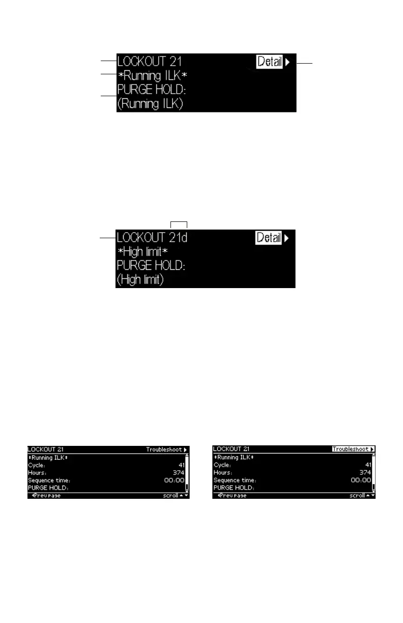
FAULT CODE
GO TO
LOCKOUT
DETAIL
DESCRIPTION
STATE AT TIME
OF FAULT
Fig. 22. Lockout message
Up to 4 lines are displayed in the standard lockout message. The top line shows the
numeric fault code that determined the lockout. A description of this fault is shown on the
second line and possibly on the third line if the description requires two lines to display
it (only one line needed in the above example). On the next line(s) the burner control
sequence state at the time of the lockout is displayed. The sequence state may need 1 or 2
lines to display (Fig. 22 required two lines). Since a maximum of 4 lines are displayed in this
message, in the case when both the fault description and sequence state each need 2 lines
to display their text, the second line of the sequence state is dropped to make room.
FAULT CODE
ANNUNCIATED
DESCRIPTION
Fig. 23. Annunciated lockout message
When an annunciator is connected to the burner control system it may annunciate the
lockout to provide more detailed information regarding the lockout. In this case the fault
code is annunciated with a fault code letter and the fault description identifies more
specifically the cause of the fault (see Fig. 23 for an example).
On the top line of the message the input focus is on a flashing “Detail” tab that permits
the user to view more details about the lockout. Pressing the “Right arrow” or “OK” button
navigates to a Lockout Detail page (see the following figure) that provides the following
information:
• Fault code
• Fault description
• Cycle count at the time of the fault
• Run-time hours at the time of the fault
• Sequence time at the time of the fault
• Operation sequence state at the time of the fault
Fig. 24. Lockout detail
The information may take more lines to display than can fit on the 5 main body lines. In this
case the a scroll bar is displayed, and the up and down arrow buttons can be used to scroll
to view all lines.
A flashing “Troubleshoot” tab is displayed in the title bar that has input focus to indicate
that the troubleshooting guide can be navigated to display what is recommended for this
fault (see Fig. 25).

 Loading...


