Do you have a question about the Honeywell AlarmNet 7845i-GSM and is the answer not in the manual?
| Weight | 0.5 lbs |
|---|---|
| Type | Alarm Communicator |
| Compatibility | Honeywell Control Panels |
| Communication | GSM |
| Frequency | 850/1900 MHz |
| Power Supply | 12V DC |
| Backup Battery | Lithium-ion rechargeable |
| Operating Temperature | 0°C to 49°C (32°F to 120°F) |
Details the Honeywell 7845i-GSM as an advanced Internet/GSM communication module for security systems.
Explains how the 7845i-GSM uses Internet and GSM services for communication, including fallback to SMS.
Describes AlarmNet-I as an encrypted, secure method for delivering alarm messages to AlarmNet equipped central stations.
Covers the 7845i-GSM's support for private key encryption, specifically 256-bit AES (Rijndael) encryption.
Highlights key features like CAT-5 connection, firewall compatibility, IP addressing, and control panel connection.
Introduces the four modes: ECP Mode, Zone Trigger Mode, 4204 Emulation Mode, and Two-4204 Emulation Mode.
Details supervision and fault detection, including network communication failure and communication path failure.
Provides technical specifications for Mechanical, Electrical, RF, Ethernet, and Environmental aspects of the device.
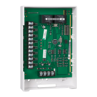
Provides instructions for indoor mounting of the 7845i-GSM, including unpacking and securing the unit.
Details how to connect the 7845i-GSM to compatible control panels via ECP bus, parallel to keypads.
Explains specific wiring connections for ECP or 4204 modes, referencing diagrams and tables.
Covers connections for zone trigger mode, including voltage trigger levels and wiring to zone inputs.
Describes how to wire and program the module's fault output trigger for fail-safe mode and fault detection.
Details the Ethernet cable connection between the 7845i-GSM and the router, including UL installation requirements.
Explains primary power connection via transformer and auxiliary power from the control panel for ECP communication.
Details the installation and function of the backup battery for system power loss, including charging and low battery reporting.
Outlines the steps before applying power, including checking terminal connections and battery installation.
Explains the 7845i-GSM's function for alarm delivery via Internet/GSM and its encryption capabilities.
Guides on connecting and using the 7720P Programming Tool, including key functions and prompts.
Covers programming conventions, ECP mode setup, password entry, and device mode selection.
Details primary/secondary account info, network settings (IP, Subnet, Gateway, DNS), and Direct Wire setup.
Configures zone inputs, trigger types, reporting delays, fault reporting, and alarm retry times.
Lists ECP status codes for module conditions and guides on reviewing programming entries.
Explains the mandatory registration process for the 7845i-GSM to enable its account and activate services.
Details how to perform registration using the 7720P Programming Tool, including monitoring the process and potential errors.
Introduces commands for viewing connectivity settings and options via the 7720P Programming Tool.
Provides commands to retrieve MAC Address, MAC CRC, SCID, and IMEI for module identification.
Shows whether the device has a physical connection to the internet, accessed via specific commands.
Displays IP address, Subnet Mask, Gateway IP, and DNS Server IP details for the module.
Presents GSM status information, including RSSI, GPRS availability, and network registration status.
Shows zone and system fault status for different operating modes like ECP, 4204, and Zone Trigger.
Covers displaying line voltage, sending test alarms, and resetting the 7845i-GSM module.
Explains how to initiate network diagnostic tests to check the integrity of links between the 7845i-GSM and AlarmNet.
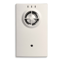
Details the 7845i-GSM Status Display LEDs (STATUS, MESSAGE, FAULT) and their states.
Provides detailed descriptions of LED states (ON, OFF, BLINK) for Status, Message, and Fault indicators.
Describes the Network Connectivity LED display for viewing network activity when the cover is removed.
Explains how RSSI/Mode and Status LEDs indicate signal strength and allow viewing of mode and carrier status.
Lists messages sent by the 7845i-GSM for various alarm conditions, categorized by mode.
Explains high-speed up/downloading capabilities for Honeywell panels via Direct Wire or ECP bus.
Details requirements and cable connections for IP downloading using the Direct Wire feature.
Provides definitions for technical terms and acronyms used throughout the manual.
Details the warranty period, coverage, limitations, exclusions, and customer responsibilities for the product.