7800 SERIESS7800A2142 4Line LCD Keyboard Display Module
320011007 6
(b) Remote Reset leadwires: The
maximum length wire is 1000 ft
(300m) to a Remote Reset push-
button.
8. Install all electrical connectors.
9. Restore power to the panel.
KDM Display
The first line of the KDM display provides
current status of the burner sequence
(STANDBY, PURGE, PILOT IGN, MAIN IGN,
RUN and POSTPURGE), timing information
(PURGE, PILOT IGN, MAIN IGN and
POSTPURGE) in minutes and seconds, hold
information (PURGE HOLD), and lockout
information (Lockout, Fault Code, Message
and Sequence). The second line will display
selectable or preemptive messages. A
selectable message supplies information
for flame strength, system status
indication, system or self-diagnostics and
troubleshooting. A preemptive message
has parentheses around the message and
supplies a detailed message to support the
sequence status information. A preemptive
message can also be a lockout message. A
preemptive message replaces a selectable
message to support the sequence status
information. The 7800 SERIES Relay
Module LED provide positive visual
indication of the Relay Module sequence.
The LED is energized simultaneously with
the correct sequence description.
1
1
2
3
3
2
120 OHM
RESISTOR
1
120 OHM
RESISTOR
A
B
A
B
C (GND)
+13 VDC
RESET
C (GND)
+13 VDC
RESET
1
23
4
5
1
23
4
5
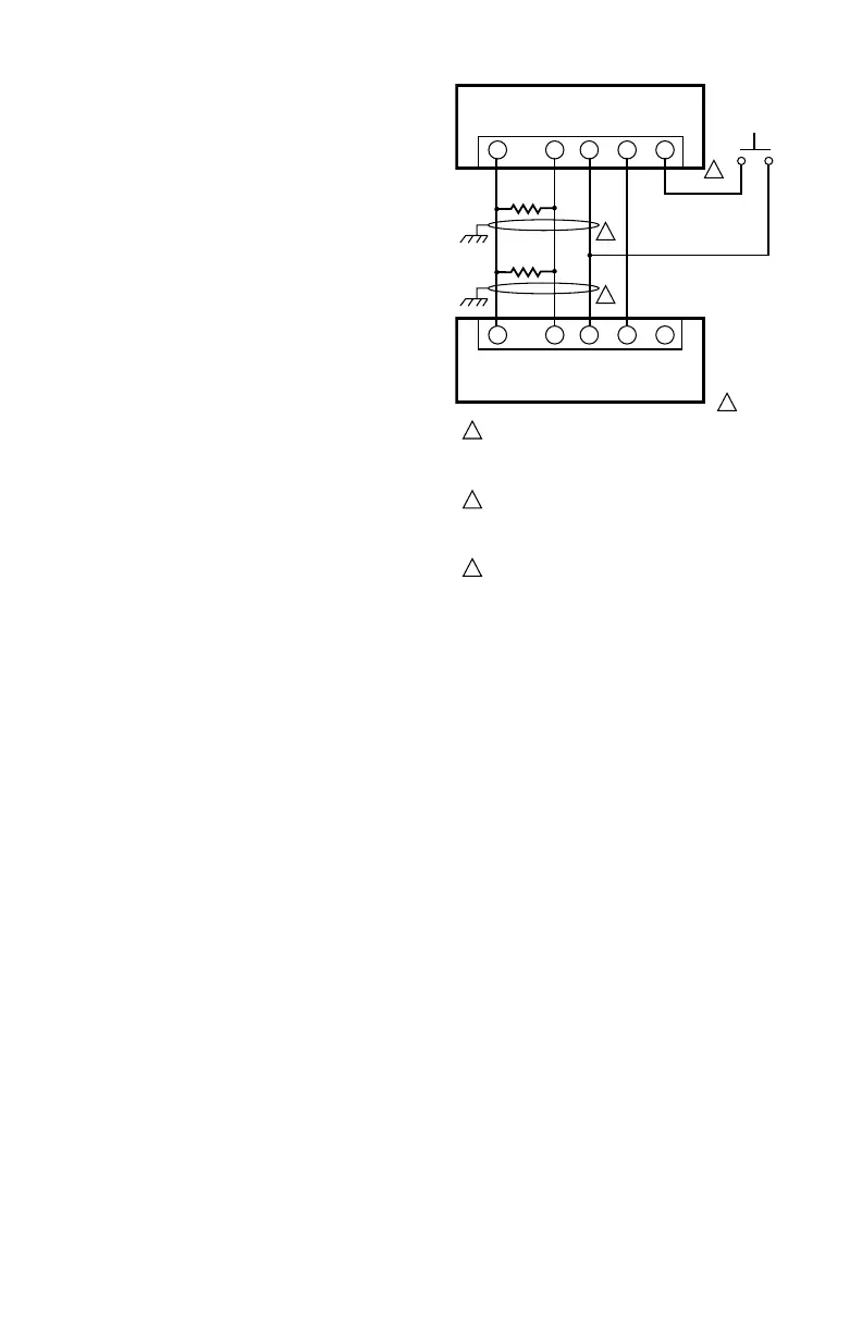
MOMENTARY
PUSH BUTTON
SWITCH
S7810 DATA CONTROLBUS MODULEª
(MOUNTED ON 7800 SERIES RELAY MODULE)
7800 REMOTE KEYBOARD DISPLAY MODULE
THREE WIRE SHIELDED CABLE MAY BE REQUIRED. TWO 120
OHM TERMINATING RESISTORS ARE REQUIRED FOR
CONNECTIONS OVER 100 FEET. CABLE SHIELD MUST BE
TERMINATED TO EARTH GROUND AT BOTH ENDS. IF SHIELDED
CABLE IS NOT USED, TWISTED PAIR WIRE MUST BE USED.
M5285C
WHEN CONNECTING THE KEYBOARD DISPLAY MODULE DATA
CONTROLBUS MODULEª, OR REMOTE RESET MODULE
EXTERNAL FROM THE CONTROL CABINET, APPROPRIAT E
MEASURES MUST BE TAKEN TO MEET EN60730 SAFETY
LOW VOLTAGE REQUIREMENTS (SEE APPROVALS).
221818A OR C EXTENSION CAN BE USED IN PLACE OF THE
S7810 DATA CONTROLBUS MODULEª IF DISPLAY IS TO
Fig. 3. Wiring Keyboard Display Module for remote
mounting.

 Loading...


