RM7885A 7800 SERIES RELAY MODULES
13 32-00215—01
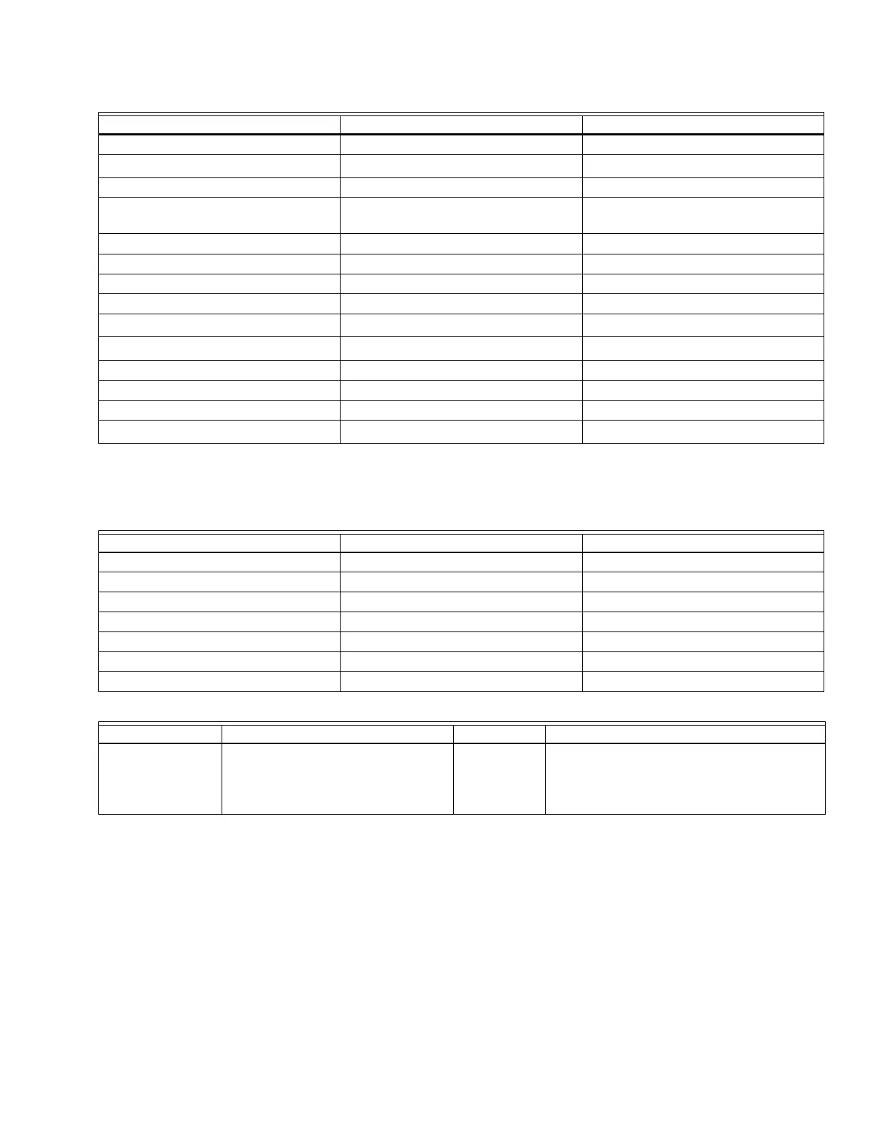
Table 4. Terminal Ratings.
a
See Table 2.
b
2000 VA maximum connected load to RM7885A Assembly.
c
See Tables 5 and 6 for device load combination for terminals 8 and 9.
Table 5. Combination for Terminals 8 and 9.
Table 6. Composition of Each Combination.
Mounting RM7885A Relay Module
1. Mount the RM7885A vertically on the Q7800
Subbase, or mount horizontally with the knife blade
terminals pointing down. When mounted on the
Q7800A, the RM7885A must be in an electrical
enclosure.
2. When mounting in an electrical enclosure, provide
adequate clearance for servicing, installation and
removal of the RM7885A, KDM, flame amplifier,
flame amplifier signal voltage probes, electrical
signal voltage probes, and electrical connections.
a. Allow an additional two inches (51 mm) below
the RM7885A for the flame amplifier mounting.
b. Allow an optional three-inch (76 mm) minimum
to both sides of the RM7885A for electrical sig-
nal voltage probes.
3. Make sure no subbase wiring is projecting beyond
the terminal blocks. Tuck in wiring against the back
of the subbase so it does not interfere with the knife
blade terminals or bifurcated contacts.
IMPORTANT
The RM7885A must be installed with a plug-in
motion rather than a hinge action.
Terminal No. Description Ratings
G Flame Sensor Ground —
Earth G
Earth Ground
a
—
L2(N) Line Voltage Common —
3 Line Voltage Supply (L1) 120 Vac (+10/-15%), 50/60 Hz,
±10%).
b
4 Alarm 120 Vac, 1A pilot duty.
5Unused.—
6 Stop Station 120 Vac,8A run, 43A inrush.
7Unused—
8Pilot Valve
120 Vac.
c
9Main Fuel Valve
120 Vac.
c
10 Start Input 120 Vac.
F(11) Flame Sensor 60 to 220 Vac, current limited.
12-21 Unused —
22 Shutter
120 VAc, 0.5A.
Combination Pilot Fuel 8 Main 9
1BD
2AD
3DNo Load
4DD
5CD
6CC
7CNo Load
ABC D
%0 VA Pilot Duty
plus 4.5A ignition.
180 VA ignition plus Motor Valves
with:
660 VA inrush,
360 VA open,
250 VA hold.
2A Pilot Duty. 65 VA Pilot Duty plus Motor Valves with:
3850 VA inrush,
700 VA open,
250 VA hold.

 Loading...


