RM7885A 7800 SERIES RELAY MODULES
5 32-00215—01
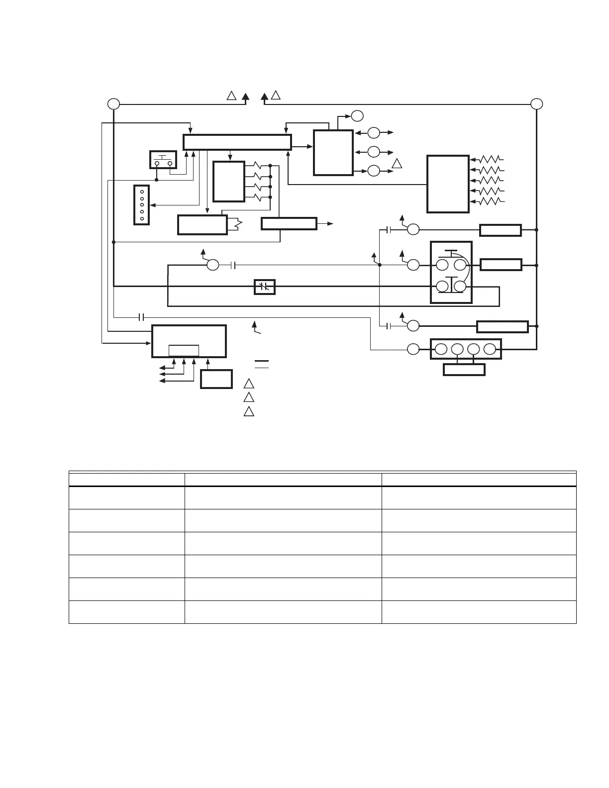
Fig. 2. Internal block diagram of RM7885A (see Fig. 2 through 6 for detailed wiring instructions).
Table 1. Recommended Wire Sizes and Part Numbers.
The Keyboard Display Module, Data ControlBus Module™
(for remote mounting or communications) or
Communication Interface ControlBus Module must be
wired in a daisy chain configuration, (1(a)-1(a), 2(b)-2(b),
3(c)-3(c)). The order of interconnection of all the devices
listed above is not important. Be aware that modules on
the closest and farthest end of the daisy chain
configuration string require a 120 ohm (1/4 watt
minimum) resistor termination across terminals 1 and 2 of
the electrical connectors for connections over 100 feet (31
meters).
Application Recommended Wire Size Recommended Part Numbers
Line voltage terminals 14, 16, or 18 AWG copper conductor, 600 volt
insulation, moisture-resistant wire.
TTW60C, THW75C, THHN90C.
Keyboard Display Module 22 AWG two-wire twisted pair with ground, or
five-wire.
Belden 8723 shielded cable or equivalent.
Data ControlBus Module™ 22 AWG two-wire twisted pair with ground, or
five-wire.
Belden 8723 shielded cable or equivalent.
Remote Reset Module 22 AWG two-wire twisted pair, insulated for
low voltage.
—
Communication Interface
ControlBus™ Module
22 AWG two-wire twisted pair with ground. Belden 8723 shielded cable or equivalent.
13 Vdc full-wave rectified
transformer power input
18 AWG wire insulated for voltages and
temperatures for given application.
TTW60C, THW75C, THHN90C.
MICROCOMPUTER
RESET
PUSH-
BUTTON
STATUS LED
SAFETY RELAY
CIRCUIT
POWER SUPPLY
OPTIONAL KEYBOARD
DISPLAY MODULE
PLUG-IN
FLAME
AMPLIFIER
RELAY
DRIVE
CIRCUIT
CONTROL
POWER
TEST
JACK
REMOTE
RESET
DDL
DDL
COMMUNICATIONS
INDICATES FEEDBACK SENSING
TO RELAY STATUS FEEDBACK
AND LINE VOLT INPUTS
FIELD WIRING
INTERNAL WIRING
IGNITION
PILOT
MAIN VALVE(S)
1K
RELAY
STATUS
FEEDBACK
AND LINE
VOLTAGE
INPUTS
LIMITS
1K1
FLAME SIGNAL
TEST
PROVIDE DISCONNECT MEANS AND OVERLOAD PROTECTION AS REQUIRED.
RM7885: 120 VAC, 50/60 HZ; EC7885A: 220-240 VAC, 50/60 HZ.
EC7885A RELAY MODULE REQUIRES A 220/240 VAC TO 120 VAC, 10 VA, STEPDOWN
TRANSFORMER (NOT SUPPLIED) TO DRIVE THE SHUTTER ON C7012E,F,
C7061A AND C7076A,D FLAME DETECTORS.
RS485
1
2
3
L1
(HOT)
L2
3
6
2K2
4K1
10
8
9
4K
5K
3K
2K
F
G
22
1
ALARM
3K1
4
L2
1
M5133D
CD
A
B
S445A
STOP
START
4
562
R4155A
2
2
3
3

 Loading...


