K9485V1 10/05 Rev.
Recessed Door Transmitter
INSTALLATION AND SETUP GUIDE
EXTERNAL PHYSICAL BARRIER
(e.g. MOLDING)
1/2" MAXIMUM
MAGNET
"IN" SIDE OF
DOOR
5818MN TRANSMITTER
5818MN-002-V1
FRAME OF
DOOR
Figure 1: Door Installation
GENERAL INFORMATION
The 5818MNL Recessed Door Transmitter is a single-
zone, reed switch magnetic contact sensor that
provides concealed protection for a door. It is intended
for use only with alarm systems that support 5800
series devices.
The transmitter is powered by one AAA Lithium (or
alkaline) battery that is easily replaced when a low
battery condition is indicated by the control panel.
PROGRAMMING
Each 5818MNL has its own unique identification code
(serial number) permanently assigned during
manufacture.
You must “enroll” the transmitter’s serial number in the
control panel before it will operate in the system.
NOTE: During programming of the control panel,
5818MNL transmitters must be enrolled as Input Type
3 (Supervised RF), Loop 1 (mandatory for UL
installations).
INSTALLATION
NOTE: Do not use on metal frame doors.
Mounting
Before selecting the mounting location, please read
the following:
• The preferred direction of mounting is vertical,
although the 5818MNL may be mounted in any
direction if satisfactory reception of its
transmissions is obtained.
•
••
• A physical barrier (e.g., a molding strip on the
door frame) should be present to protect against
defeat of the contact from outside the premises.
•
••
• Make sure that no more than 1/2” gap exists
between the faces of the transmitter and magnet
cases when they are installed and set.
•
••
• Once installed, an alarm signal must be
obtained before a separation of 2” is reached
as the door is opened.
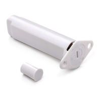
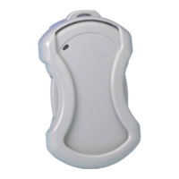
TRANSMITTER
CASE
ANTENNA
END CAP
REED
SWITCH
PC BOARD
5818MN-001-V0
Figure 2: Battery/Transmitter Assembly
1. Select a location for the transmitter on the door
frame (never on the hinged edge). CAUTION: Do
not install in the door.
2. Select the location for the magnet on the door,
directly opposite the transmitter location.
3. Tape the transmitter and magnet in their
approximate locations (with battery installed and
unit together as described in the BATTERY
INSTALLATION / REPLACEMENT section below
and conduct Go/No Go tests (refer to control
panel’s instructions) to verify adequate signal
strength. Reorient or relocate transmitter if
necessary.
4. Mark the selected locations.
5. Drill holes at the locations marked. The transmitter
will require a 3/4” diameter hole in the edge of the
frame, at least 3” deep. The magnet will require a
3/8” diameter hole in the edge of the door at least
1/2” deep.
6. Insert the transmitter and magnet cases into
their respective holes, so that their ends are flush
with the surface.
• DO NOT hammer in place with hard blows. If
necessary, tap gently with a rubber mallet or
wood block.
• The transmitter case may be secured by two #4
flat head, self-tapping screws via the holes in its
mounting flanges, or the flanges can be
snapped off by scoring around them first with a
sharp knife.
• If necessary, either case may be secured with a
suitable adhesive.
NOTE: A closure plug is supplied to cover an empty
transmitter hole if it becomes necessary to relocate
the transmitter.