LIMITED WARRANTY
Honeywell International Inc., acting through its Security & Custom Electronics business
("Seller") 165 Eileen Way, Syosset, New York 11791, warrants its product(s) to be in
conformance with its own plans and specifications and to be free from defects in materials
and workmanship under normal use and service for 24 months from the date stamp control
on the product(s) or, for product(s) not having a manufacturer’s date stamp, for 12 months
from date of original purchase unless the installation instructions or catalog sets forth a
shorter period, in which case the shorter period shall apply. Seller's obligation shall be
limited to repairing or replacing, at its option, free of charge for materials or labor, any
product(s) which is proved not in compliance with Seller's specifications or proves defective in
materials or workmanship under normal use and service. Seller shall have no obligation
under this Limited Warranty or otherwise if the product(s) is altered or improperly repaired
or serviced by anyone other than Honeywell factory service. For warranty service, return
product(s) transportation prepaid, to Honeywell Factory Service, 165 Eileen Way, Syosset,
New York 11791.
THERE ARE NO WARRANTIES, EXPRESS OR IMPLIED, OF MERCHANTABILITY, OR
FITNESS FOR A PARTICULAR PURPOSE OR OTHERWISE, WHICH EXTEND BEYOND
THE DESCRIPTION ON THE FACE HEREOF. IN NO CASE SHALL SELLER BE LIABLE
TO ANYONE FOR ANY CONSEQUENTIAL OR INCIDENTAL DAMAGES FOR BREACH
OF THIS OR ANY OTHER WARRANTY, EXPRESS OR IMPLIED, OR UPON ANY OTHER
BASIS OF LIABILITY WHATSOEVER, EVEN IF THE LOSS OR DAMAGE IS CAUSED BY
THE SELLER'S OWN NEGLIGENCE OR FAULT.
Seller does not represent that the product(s) it sells may not be compromised or
circumvented; that the product(s) will prevent any personal injury or property loss by
burglary, robbery, fire or otherwise; or that the product(s) will in all cases provide adequate
warning or protection. Customer understands that a properly installed and maintained
alarm system may only reduce the risk of a burglary, robbery, fire, or other events occurring
without providing an alarm, but it is not insurance or a guarantee that such will not occur or
that there will be no personal injury or property loss as a result. CONSEQUENTLY,
SELLER SHALL HAVE NO LIABILITY FOR ANY PERSONAL INJURY, PROPERTY
DAMAGE OR OTHER LOSS BASED ON A CLAIM THAT THE PRODUCT(S) FAILED TO
GIVE WARNING. HOWEVER, IF SELLER IS HELD LIABLE, WHETHER DIRECTLY OR
INDIRECTLY, FOR ANY LOSS OR DAMAGE ARISING UNDER THIS LIMITED
WARRANTY OR OTHERWISE, REGARDLESS OF CAUSE OR ORIGIN, SELLER'S
MAXIMUM LIABILITY SHALL NOT IN ANY CASE EXCEED THE PURCHASE PRICE OF
THE PRODUCT(S), WHICH SHALL BE THE COMPLETE AND EXCLUSIVE REMEDY
AGAINST SELLER.
This warranty replaces any previous warranties and is the only warranty made by Seller on
this product(s). No increase or alteration, written or verbal, of the obligations of this Limited
Warranty is authorized.
165 Eileen Way, Syosset, New York 11791
Copyright © 2004 Honeywell International, Inc.
www.honeywell.com/security
¬19Ql
N6483V3 4/98 Rev. B
N6483V3 4/98 Rev. B
INSTALLATION AND SETUP GUIDE
GENERAL INFORMATION
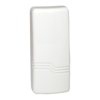
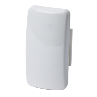
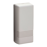
The 5817 Multi-Point Universal Transmitter may have three contact loops connected to it. Each
loop transmits a unique ID code to a 5800 wireless system receiver connected to the system
control panel. The Primary Loop has several DIP switch selectable options that determine its
connection requirements, response, and transmission characteristics (see DIP switch setting
table on next page). The two Auxiliary Loops are closed-circuit, with a nominal response time of
100mSec. For UL installations, no contact in any of the loops may be more than 3 feet from the
transmitter.
A built-in cover tamper switch is activated when the cover is removed.
ENROLLING THE TRANSMITTER IDs
The 5817 has its own unique identification codes permanently assigned during manufacture. It is
not necessary to program the transmitter IDs during installation. Instead, the control unit is
required to "enroll" the transmitter IDs at some point prior to the transmitter’s usage in the alarm
system.
The control unit’s installation manual contains general information on the "enrolling" procedure,
but the information given herein pertains specifically to the 5817.
1. Place a 3V battery in the battery holder, as described later in BATTERY
INSTALLATION/REPLACEMENT and as shown in Diagram 2. Observe polarity!
2. Make sure that the DIP switch’s 4 positions (see Diagram 2) are all OFF.
3. Set the system ready for enrolling the ID code of one of the 5817’s loops (inputs) to be
used, as described in the control’s instructions. The 5817 should be treated as "RF" (i.e.,
supervised RF) Type (mandatory for UL installations).
4. Proceed with enrolling the inputs of the loops to be used, as described in the control’s
instructions.
INSTALLATION
Mounting
For proper orientation of the unit in relation to its wall mounting plate and the loop wiring, read all
of this section before installing the unit.
The description that follows assumes that the unit will be mounted as shown in the diagrams. The
unit may, however, be installed in any direction, as long as the relationship of the unit to its
mounting plate is maintained.
Although two holes are provided in the unit that would permit mounting directly to a surface (holes
"A" in Diagram 2), it is recommended that the mounting plate be used, as described below, for
ease in removing the unit for servicing should it become necessary.
Before mounting the transmitter permanently, conduct Go/No Go tests (see control’s instructions)
to verify adequate signal strength and reorient or relocate the transmitter if necessary. When a
satisfactory location is found, remove the battery and proceed with installation.
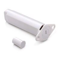
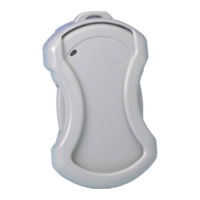
1. Remove the transmitter’s cover by inserting the flat blade of a small screwdriver into the
pry-off slot at the end of the unit farthest from the cover’s decorative ribs, and twisting the
blade. Note: The open slot at the other end of the unit cannot be used as a cover pry-off.
2. Disengage the supplied mounting plate from the unit by inserting the blade of a small
screwdriver into the locking tab release window (see Diagram 2) and pressing it against the
case locking tab (see Diagram 1) while sliding the plate downward along the case back. Note:
For this application, the alignment guide strip along one edge of the plate serves no function
and may be broken away, if desired.