K5503V2 4/08 Rev.
DEMCO 5815
DOOR/WINDOW TRANSMITTE
INSTALLATION
INSTRUCTIONS
5815-01-V0
LOCKING
TA B
RELEASE
WINDOW
COVER PRY-OFF SLOT
MOUNTING
PLATE
HOLES (2)
OBSERVE POLARITY
LOCKING
TAB
WIRES
MOUNTING PLATE
CASE
COVER
RETAINING
HOOKS
(3)
POST (2)
WIRE
BREAKOUT
(2)
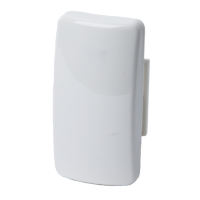
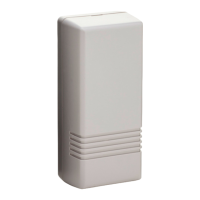
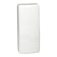
Figure 1. Mounting Plate and Case
GENERAL INFORMATION
The Honeywell Ademco 5815 is a two-zone
Door/Window Transmitter that has its own unique serial
number. The control unit is required to "enroll" the serial
number prior to its usage in the alarm system. Refer to
the control unit's installation instructions for further
details.
Note:
During programming of the control unit,
5815 transmitters should be treated as "RF" (i.e.,
supervised RF) Type (
mandatory for UL installations
).
The 5815 provides two input loops (zones): the
first
for a
wired closed-circuit contact loop, and the
second
for its
built-in reed switch (used in conjunction with a magnet,
as described below). One or both inputs may be used.
For UL installations, a contact may not be more than 3
feet from the transmitter.
The 5815 includes a built-in cover tamper, which is
activated when the cover is removed.
MOUNTING
For proper orientation of the unit in relation to the
mounting plate, loop wiring, and/or magnet, read all of
this section before installing the unit.
The description that follows assumes that the unit will be
mounted as shown in the diagrams, with the magnet (if
used) located in one of the positions shown in Figure 2.
The unit may, however, be installed in
any
direction, as
long as the relationship of the unit to its mounting plate
and (if used) magnet is maintained.
Although the unit can be mounted directly to a surface,
we recommend that the mounting plate be used, for
ease in removing the unit for servicing should it become
necessary.
Before mounting the transmitter permanently, conduct
Go/No Go tests (see control's instructions) to verify
adequate signal strength and reorient or relocate the
transmitter if necessary.
1. Remove the transmitter's top cover by inserting
the flat blade of a small screwdriver into the pry-off
slot at one end of the unit (see Fig. 1 for location),
and slightly twisting the blade until the cover
disengages.
IMPORTANT: DO NOT REMOVE
the circuit board from
the back case plastic.
5815-002-V0
LOOP
TERMINALS
(LOOP 1)
LITHIUM BATTERY
CR1-335 (3V)
COVER
RETAINING
HOOKS (3)
ANNTENNA
+
+
COVER
PRY-OFF
SLOT
WIRE ENTRY
HOLE
TAMPER
SWITCH
IC
CRYSTAL
REED
SWITCH
(LOOP 2)
REED
SWITCH
(LOOP 2)
(ALTERNATE POSITION
FOR MAGNET)*
*MAGNET
(OBTAIN
SEPARATELY)
+
_
* MAGNET MUST BE WITHIN
1/2" OF REED SWITCH
Figure 2. 5815 (shown without cover)
2. Disengage the attached mounting plate from the
case by inserting the blade of a small screwdriver
into the locking tab release window (see Figure 1)
and pressing it against the locking tab (also shown in
Figure 1), while sliding the mounting plate upward
along the case back until free.
3. Install the mounting plate, with its two case-
holding posts pointing up (in this example), in the
location selected as described in the control panel's
installation instructions. Use the flat-head screws
supplied.
Note:
If a wired contact loop is to be used, with
concealed
wiring, the wire exit hole in the wall must
be located under the wire entry hole in the case as
shown in Figure 2, and no more than 1/4" in
diameter.
4. If a wired contact loop is to be used, feed
concealed
wiring through the slot in the case back,
but do not connect to the terminal block yet. For
surface
wiring entry, two thin "breakout" areas are
provided in the case wall (see Figure 1).
5. Attach the case back to the mounting plate by
sliding the keyhole slots in the case back down onto
the mounting plate's case holding posts. The locking
tab will click as the case back locks in place.
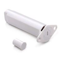
6. If a reed switch is to be used, mount a No. 5899
Magnet (obtained separately) adjacent to the reed
switch, or adjacent to the top of the case (see Figure
2). In either case, the magnet must be mounted
within one-half inch of the reed switch.
LOOP WIRING CONNECTIONS (If used)
With the battery still not inserted, connect the contact
loop wires to the unit's loop terminals (see Figure 2).
Caution: Make sure that the bared sections of the
loop wires do not short to the reed switch or
antenna.
The contact loop must use closed-circuit devices.
The
loop response time is a nominal 100mSec.
NOTE: If the contact loop is not to be used, no
connection is needed across the loop terminals.