© Honeywell LT-ACM-II-03 Rev. A
Ethernet connections
The ACM has two RJ-45 jacks that support 10BASE-T
(10 Mbps), 100BASE-TX (100 Mbps), and 1000BASE-T
(1000 Mbps) Ethernet connections. The ACM
automatically operates at 1000 Mbps if other devices and
cabling support it.
MS/TP connections
MS/TP is a LAN standard designed specifically for
BACnet applications. It uses the EIA–485 signaling
standard on twisted-pair cabling in a simple bus
configuration.
Binary Input and Analog Input
ACMs have two terminal blocks for connecting analog
and binary monitoring inputs. Each terminal block has
three screw-connections. The terminals are:
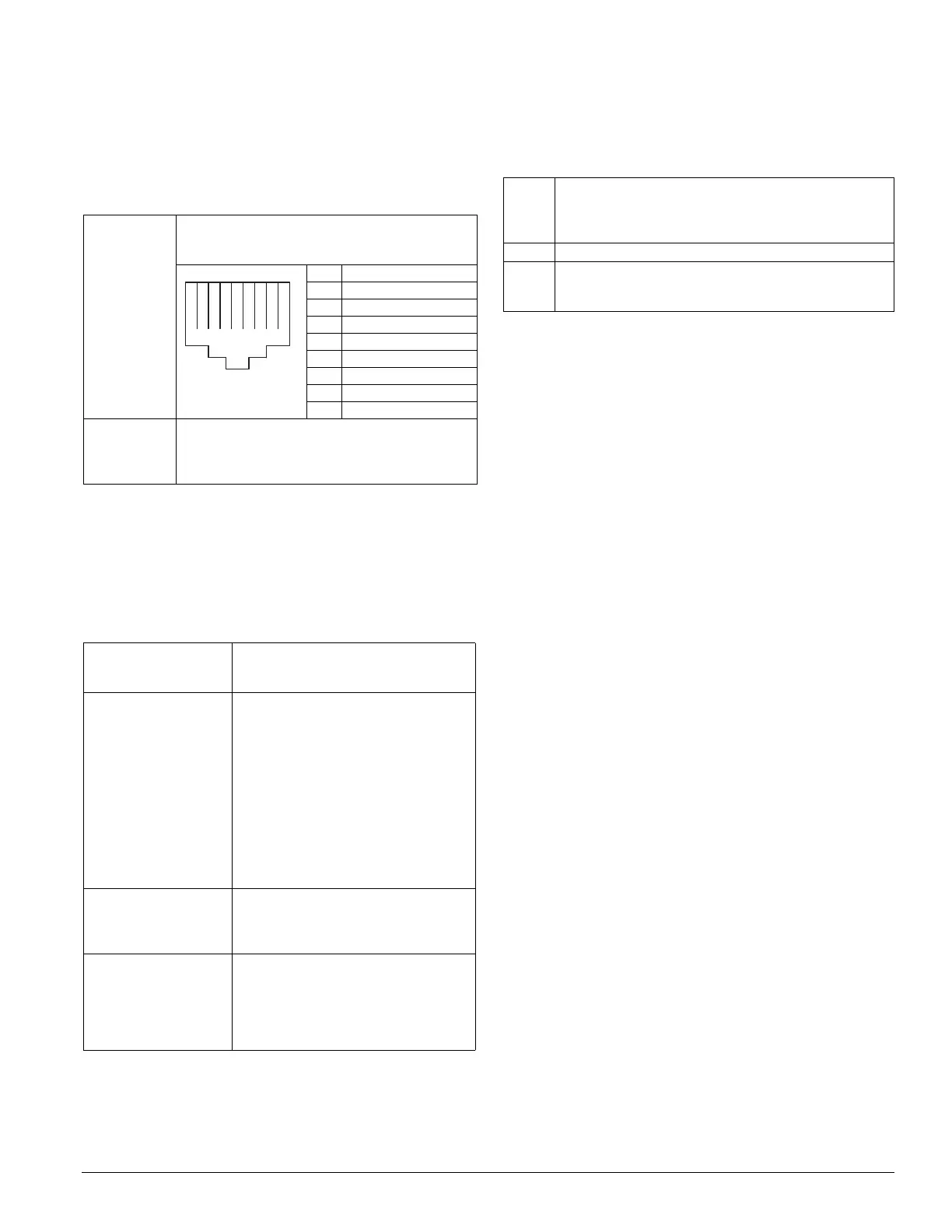
Table 1 Ethernet connections
Ethernet RJ-
45 jack
An RJ-45 jack for connection to Ethernet is on top of
the ACM. Pin designations for the RJ-45 jack are
shown.
Pin Assignment
1 Bi-directional pair A+
2 Bi-directional pair A-
3 Bi-directional pair B+
4 Bi-directional pair C+
5 Bi-directional pair C-
6 Bi-directional pair B-
7 Bi-directional pair D+
8 Bi-directional pair D-
Cable type
and length
Use an approved Category 5e or better Ethernet drop
cable with RJ-45 plugs. Use professionally
manufactured cables of no more than 328 feet (100
meters).
Table 2 MS/TP connections
Terminal identification Terminals for MS/TP are on the top edge of
modules and are labeled
MS/TP + and MS/TP –.
Cable type and length BACnet specifies shielded, twisted-pair
cabling with characteristic impedance
between 100 and
130 Ohms. Distributed capacitance
between conductors must be less than 30
pF/foot (100 pF/m). Distributed
capacitance between conductor and shield
must be less than 60 pF/foot (200 pF/m).
Foil or braided shield is acceptable.
Cable length should be 4000 feet (1200
meters) per segment. Maintain polarity
throughout the MS/TP segment.
Terminating resistors Matched precision resistors are required at
each end of the MS/TP segment. Wire the
resistors across + and –. Tune the MS/TP
LAN to obtain optimum resistor values.
Shield grounding Terminate shield drain at one end of the
MS/TP segment to ground. Tie shield drain
through with wire nut at each intermediate
device and insulate to avoid potential
ground contact. Tape shield drain back at
other end of segment.
+‒ ‒ ‒ ‒+++
12345678
Table 3 Binary Input (BI) and Analog Input (AI)
IN-0
IN-1
Support 10k ohm thermistor, non-pulse dry-contact, and 0-
10vDC input signals to monitor inputs such as outdoor
temperature or relative humidity. Can handle 4-20mA with an
external resistor.
COM Common terminals for their blocks.
BI-2
BI-3
Support non-pulse dry-contact input signals. Can also be
configured to monitor any binary status point, such as a Fire
Alarm dry contact or a door switch.

 Loading...