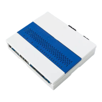
Do you have a question about the Honeywell ACS-2plus and is the answer not in the manual?
Guidelines for installing the ACS-2 plus and adding extensions, emphasizing safety.
Measures to protect against damage from static electricity during handling and installation.
Methods to safeguard against atmospheric overvoltages and switching transients.
Guidance on proper grounding and shielding to prevent interference and ensure system integrity.
Details on using shielded cables and the correct shielding connection method for data lines.
Information on power supply requirements for 230V and 12V versions, including cable types and voltage drop calculations.
Conditions to consider for the central unit's installation location for optimal performance and safety.
Step-by-step guide for physically mounting the ACS-2 plus unit, including housing removal.
Procedure for installing or replacing interface cards, including safety precautions before touching components.
Detailed instructions and safety warnings for replacing the lithium battery to preserve data.
Steps for replacing the battery, resetting tamper alarms via software, and confirming battery status.
Table detailing DIP switch S1 configurations for setting device addresses from 1 to 32.
Configuration options for protocol and baud rate using DIP switch S1, including factory settings.
Configuration settings for reader types (e.g., pull-down/pull-up) using DIP switch S2.
Methodology for determining the necessary memory based on ID cards, bookings, and system features.
Finalizing total memory calculation and analyzing the need for RAM extension modules.
Sequence of steps required to commission the ACS-2 plus, including battery, mains, bootstrap, and setup.
Procedure for setting up the ACS-2 plus using a terminal program via serial interface.
Accessing the ACS-2 plus setup menu via APPL_Login or BOOT_Login, with timing requirements.
Configuring communication parameters like protocol, baud rate, address, and group address.
Identification and function of LEDs, buzzer, and the push-button on the ACS-2 plus LED board.
Detailed table explaining the state and meaning of each LED and the buzzer for the ACS-2 plus.
Wiring instructions for fail-secure door strikes with load current, including tamper monitoring setup.
Wiring instructions for fail-safe door strikes (no-load current), noting limitations for tamper monitoring.
A detailed example illustrating the calculation of memory requirements for ACS-2 plus controllers.
| Number of Outputs | 4 |
|---|---|
| Communication | RS-485 |
| Outputs | 4 |
| Reader Support | Wiegand |
| Power Supply | 12 VDC |
| Input Voltage | 12 VDC |
| Humidity Range | 95% non-condensing |
| Communication Protocol | RS-485 |


